background image

Dx350_06d_oi_e.docx / Jul-20 


page 23 / 67 


General Menu 


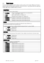
OPERATIONAL MODE 

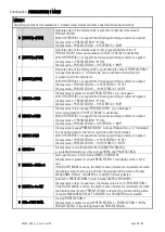
This parameter specifies the selected measuring function. 
 

0  SPEED 

Speed indicator (RPM), tachometer or frequency counter 

1  PROCESS TIME 

Operation as baking time or processing time indicator (reciprocal speed)  

2  TIMER 

Operation as stopwatch 

3  COUNTER 

Operation as position indicator, event-, sum-, differential- or up-down counter 

4  VELOCITY 

Runtime measurement as speed indicator 


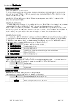
ENCODER PROPERTIES


(for DX350)


This parameter determines the characteristics of the pulse input for DX350.


0  PNP 

PNP (switch to +) 

1  NPN 

NPN (switch to -) 

2  NAMUR 

Connect sensor (–) to GND and sensor (+) to input (A or B) 

3  TRI-STATE 

Tri-State for push-pull encoders/ sensors 


ENCODER PROPERTIES


(for DX355)


This parameter determines the characteristics of the pulse input for DX355.


0  RS422 

RS422 standard 

1  HTL DIFFERENTIAL 

HTL differential 

2  HTL PNP 

HTL PNP single ended (switch to +) 

3  HTL NPN 

HTL NPN single ended (switch to -) 


ENCODER SUPPLY


(only for DX355 available)


This parameter defines the voltage of the auxiliary supply output (Aux-Out). 


0  24VDC SUPPLY 

24 VDC encoder supply  


1  5VDC SUPPLY 

5 VDC encoder supply 


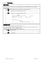
COUNTING DIRECTION


This parameter determines the direction of counting. (Only in mode COUNTER)


0  FORWARD 

forward 

1  REVERSE 

reverse 


Содержание DX350

Страница 1: ...lay inclusively icons and units Intuitive and easy parameterization by plain text and touchscreen 5 24 V auxiliary output for encoder supply Input frequencies up to 1 MHz Linearization with 24 interpo...

Страница 2: ...on DX350_01d_oi cn Okt 16 Revised first Version DX350_02a_oi cn Nov 16 Second Version DX350_02c_oi cn Jan 17 Revised Version DX350_03a_oi cn Apr 17 Revised Version DX350_03b_oi cn Jun 17 Other small c...

Страница 3: ...ts included in this manual are protected by the terms of use and copyrights of motrona GmbH Any reproduction modification usage or publication in other electronic and printed media as well as in the i...

Страница 4: ...nterface Option AO AR CO CR 15 Control Output AO AR CO CR 15 AC Power supply Option AC 16 Relay Output Option RL 16 Display and touch screen 17 Screen structure for parametrization 17 Screen structure...

Страница 5: ...Dx350_06d_oi_e docx Jul 20 page 5 67 Diagnostics 57 Parameter serial codes 58 Linearization 63 Dimensions 65 Technical specifications 66...

Страница 6: ...rves the right to modify the hardware software or operation manual at any time and without prior notice Therefore there might be minor differences between the unit and the descriptions in operation ma...

Страница 7: ...further indicated as separator Incoming as well as outgoing wires and wires for extra low voltages ELV must be separated from dangerous electrical cables SELV circuits by using a double resp increased...

Страница 8: ...be mounted in a metal enclosure with sufficient distance to sources of electromagnetic noise Run signal and control cables apart from power lines and other cables emitting electromagnetic noise Please...

Страница 9: ...of frequency RMP indicator Monitoring functions for speed and standstill PROCESS TIME only input A is used Processing time indicator reciprocal speed Baking time indicator Flow time indicator TIMER on...

Страница 10: ...Dx350_06d_oi_e docx Jul 20 page 10 67 Function diagram...

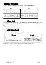
Страница 11: ...l GND terminals are internally interconnected Auxiliary Voltage Output Terminal 3 and 4 provide an auxiliary output for supply of sensors and encoders The output voltage depends on the power supply DC...

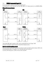
Страница 12: ...PNP NPN Namur Tri State Unconnected PNP inputs are always LOW and unconnected NPN inputs are always HIGH All inputs are designed to receive impulses from electrical impulse sources Notice for mechani...

Страница 13: ...2 signals The characteristics of the incremental input can be set in the GENERAL MENU Wiring of the incremental inputs RS422 HTL DIFFERENTIAL HTL PNP single ended HTL NPN single ended Unconnected PNP...

Страница 14: ...ng contacts When exceptionally mechanical contacts are used please connect an external capacitor between GND and the corresponding input A capacity of 10 F will reduce the input frequency to 20 Hz and...

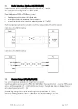
Страница 15: ...shows the connection to a PC by using a standard Sub D 9 connector Connection of the RS232 interface Connection of the RS485 interface Control Output AO AR CO CR Four control outputs are available at...

Страница 16: ...age output Devices with option AC can also be supplied with a DC voltage between 18 and 30 VDC at terminals 1 and 2 Relay Output Option RL Two relay outputs with potential free changeover contacts are...

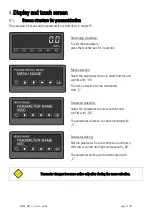
Страница 17: ...ect the parameter menu via arrow buttons and confirm with OK The menu selection can be terminated with C Parameter selection Select the parameter via arrow buttons and confirm with OK The parameter se...

Страница 18: ...top of the screen This is only possible in operation mode COUNTER A B A B or BATCH TOTAL MODE is active or in operation mode TIMER TOTAL TIME MODE is active Two line display with units To switch to t...

Страница 19: ...ble with option AO CO RL Display with minimum and maximum value To switch to the next display press the top of the screen or the skip button Error messages ERROR MAXIMUM DISPLAY VALUE The display valu...

Страница 20: ...is greater than 99 999 999 ERROR MIN DOWN DISPLAY VALUE Down display value of the two line display is less than 99 999 999 ERROR MAX LARGE DISPLAY VALUE The display value of the large display is grea...

Страница 21: ...AL MODE ENCODER PROPERTIES ENCODER SUPPLY COUNTING DIRECTION SCALE UNITS SCALE UNITS BATCH LINEARIZATION MODE PIN PRESELECTION PIN PARAMETER BACK UP MEMORY FACTORY SETTINGS MODE SPEED DISPLAY VALUE BA...

Страница 22: ...Y 3 OUTPUT LOCK 3 START UP DELAY 3 EVENT COLOR 3 PRESELECTION 4 MENU SOURCE 4 MODE 4 HYSTERESIS 4 PULSE TIME 4 OUTPUT TARGET 4 OUTPUT POLARITY 4 OUTPUT LOCK 4 START UP DELAY 4 EVENT COLOR 4 Menu Param...

Страница 23: ...input for DX350 0 PNP PNP switch to 1 NPN NPN switch to 2 NAMUR Connect sensor to GND and sensor to input A or B 3 TRI STATE Tri State for push pull encoders sensors ENCODER PROPERTIES for DX355 This...

Страница 24: ...NITS BATCH 0 Hz Default 1 kHz 2 m s 3 m min 4 km h 5 mph 6 1 min 7 RPM 8 1 sec 9 RPS 10 Stk h 11 pcs h 12 mm 13 m 14 inch 15 feet 16 Stueck 17 pcs 18 sec 19 min 20 Min Sec 21 H M S 22 Min Sec 00 23 l...

Страница 25: ...N code to lock the quick start of the menu PRESELECTION VALUE for entering the preselection values Master PIN 6079 This Lock function is only useful in conjunction with active lock function in PIN PAR...

Страница 26: ...value 100 Default value 500000 Highest value DECIMAL POINT This value defines the position of the decimal point 0 NO No decimal point 1 0000000 0 Decimal point at the specified position 2 000000 00 De...

Страница 27: ...be set in PRESELECT MENU 0 00 Shortest time 99 99 Largest time AVERAGE FILTER Selectable average or filter function to avoid measuring fluctuations by unstable frequencies At setting 1 to 4 a floating...

Страница 28: ...int will be set automatically 0 SECONDS Display in seconds 1 MINUTES Display in minutes 2 MIN SEC Display in minutes seconds 3 MIN 00 Anzeige in Minuten und 1 100 Minuten 4 H M S Anzeige in Stunden Mi...

Страница 29: ...can be set in PRESELECT MENU 0 00 Shortest time 99 99 Longest time AVERAGE FILTER Selectable average or filter function to avoid measuring fluctuations by unstable frequencies At setting 1 to 4 a floa...

Страница 30: ...me measurement 0 COUNT AT A HIGH Time measurement active at Input A is HIGH 1 COUNT AT A LOW Time measurement active at Input A is LOW 2 START A STOP B A rising edge at Input A starts the time measure...

Страница 31: ...ime measurement runs parallel to the normal time measurement If the total time measurement should be automatically reset to O when 1 30 H M is reached the reference source must be set e g to SOURCE1 f...

Страница 32: ...nting x4 FACTOR Scaling factor With the summing mode A B and the differential mode A B please note that the impulse scaling factor will only affect input A For example A setting of factor 1 23456 and...

Страница 33: ...n or equal RESUL PRES Example for the total counter For the total counter BATCH TOTAL MODE must be set to TOTAL COUNTER The total counter counts here parallel to the main counter e g If the total coun...

Страница 34: ...ling edge at Input A Stop rising edge at input B DISPLAY VALUE Desired value which should be displayed at the setting of BASE TIME S 1 Smallest value 1000 Default value 999999 Highest value BASE TIME...

Страница 35: ...The display value is retained until a new value is determined 0 01 Frequency 0 Hz for frequencies below 100 Hz 99 99 Frequency 0 Hz for frequencies below 0 01 Hz STANDSTILL TIME This parameter define...

Страница 36: ...999 Smallest value 1000 Default value 99999999 Highest value PRESELECTION 2 Preselection switching point 2 99999999 Smallest value 2000 Default value 99999999 Highest value PRESELECTION 3 Preselection...

Страница 37: ...selected operating mode 1 COUNTER A Reference source is the counter reading of channel A only visible in mode COUNTER COUNT MODE A B or A B 2 COUNTER B Reference source is the counter reading of chann...

Страница 38: ...ual PRESELECTION 1 e g underspeed start up suppression START UP DELAY is advisable With HYSTERESIS 1 not equal 0 the following switching condition is applied Display value PRESELECTION 1 ON Display va...

Страница 39: ...No output pulse static signal 60 000 Pulse duration of 60 seconds OUTPUT TARGET 1 Assignment of an output or relay for the switching condition of preselection 1 If more than one switching condition is...

Страница 40: ...art Up Delay 3 and 4 have an automatic start up suppression 00 000 No start up suppression 60 000 Start up suppression in seconds EVENT COLOR 1 Event depending change of the display color for the swit...

Страница 41: ...N 1 MENU PULSE TIME 2 S Duration of output pulse for the switching condition of preselection 2 See chapter PRESELECTION 1 MENU OUTPUT TARGET 2 Assignment of an output or relay for the switching condit...

Страница 42: ...TION 1 MENU OUTPUT TARGET 3 Assignment of an output or relay for the switching condition of preselection 3 See chapter PRESELECTION 1 MENU OUTPUT POLARITY 3 Polarity for the switching condition of pre...

Страница 43: ...TION 1 MENU OUTPUT TARGET 4 Assignment of an output or relay for the switching condition of preselection 4 See chapter PRESELECTION 1 MENU OUTPUT POLARITY 4 Polarity for the switching condition of pre...

Страница 44: ...it data format 0 7 EVEN 1 7 data Parity even 1 Stop 1 7 EVEN 2 7 data Parity even 2 Stops 2 7 ODD 1 7 data Parity odd 1 Stop 3 7 ODD 2 7 data Parity odd 2 Stops 4 7 NONE 1 7 data no Parity 1 Stop 5 7...

Страница 45: ...on is stopped for 20 s 0 000 All cyclic transmission is switched off The unit will send data upon a serial request or with command SERIAL PRINT 60 000 Cycle time in seconds SERIAL VALUE This parameter...

Страница 46: ...MODE YES ANALOG FORMAT This parameter defines the output characteristics The analogue output is proportional to the display value With setting ANALOG FORMAT 10 10 V in MODE COUNTER the polarity of the...

Страница 47: ...67 Continuation Analog MENU ANALOG OFFSET This parameter defines the zero offset of the analog output z B 0 20 result in an offset of 0 02 V or 0 04 mA at ANALOG START value 99 99 Smallest offset 0 D...

Страница 48: ...ELECTION 1 4 d 18 SET GREEN COLOR The display lights up green The color can be changed by the event dependent color switching in the PRESELECTION 1 4 d 19 SET YELLOW COLOR The display lights up yellow...

Страница 49: ...DGE Activate at falling edge INPUT 2 ACTION This parameter defines the function of the input Ctrl In 2 See parameter INPUT 1 ACTION INPUT 2 CONFIG This parameter defines the switching characteristics...

Страница 50: ...y second line 0 MEASUREM RESULT Reference source is the measurement result of the selected operating mode 1 COUNTER A Reference source is the counter reading of channel A only visible in mode COUNTER...

Страница 51: ...e time FONT This parameter defines the setting of the font style 0 Standard 1 Font 1 START DISPLAY This parameter defines the start display after switching on device 0 STANDARD Display with unit and s...

Страница 52: ...splay value for the large display can be divided Applies only for all 99999999 number formats 0 NO Large display off 1 1 1 Large display with splitting ratio 1 1 2 1 10 Large display with splitting ra...

Страница 53: ...d examples are shown in the appendix P1 X P24 X X coordinate of the linearization point This value representing the display value which the unit show in the display without linearization 99999999 Smal...

Страница 54: ...To request for a data transmission you must send the following request string to the converter EOT AD1 AD2 C1 C2 ENQ EOT control character Hex 04 AD1 unit address High Byte AD2 unit address Low Byte...

Страница 55: ...ter setting Required parameter settings in DX350 DX355 Serial menu UNIT NUMMER Not valid for Modbus communication For setting of Modbus address see parameter MODBUS SERIAL BAUD RATE This parameter def...

Страница 56: ...l variables actual data and status registers are mapped to Modbus Holding Registers However as all registers of the device are 32 bit registers but Modbus Holding registers are only 16 bit registers e...

Страница 57: ...le to read and set reset single commands Coil number Serial code of command Command 0 54 Reset Set Reset Set Value 1 55 Freeze Display Freeze actual display value 2 56 Touch Disable Disable touch scre...

Страница 58: ...0 0 0 21 MODE SPEED 21 0 0 0 22 MODE PROCESS TIME DISPLAY FORMAT 22 0 3 0 23 MODE PROCESS TIME DISPLAY VALUE 23 1 99999999 1000 24 MODE PROCESS TIME BASE FREQUENCY HZ 24 1 500000 100 25 MODE PROCESS...

Страница 59: ...0 60000 0 70 PRESELECTION 1 MENU EVENT COLOR 1 C1 0 3 0 71 PRESELECTION 1 MENU C2 0 0 0 72 PRESELECTION 2 MENU SOURCE 2 C3 0 5 0 73 PRESELECTION 2 MENU MODE 2 C4 0 11 0 74 PRESELECTION 2 MENU HYSTERE...

Страница 60: ...U G5 0 0 0 119 COMMAND MENU INPUT 1 ACTION G6 0 29 0 120 COMMAND MENU INPUT 1 CONFIG G7 0 3 2 121 COMMAND MENU INPUT 2 ACTION G8 0 29 0 122 COMMAND MENU INPUT 2 CONFIG G9 0 3 2 123 COMMAND MENU INPUT...

Страница 61: ...1 99999999 99999999 0 165 LINEARIZATION MENU P13 Y L2 99999999 99999999 0 166 LINEARIZATION MENU P14 X L3 99999999 99999999 0 167 LINEARIZATION MENU P14 Y L4 99999999 99999999 0 168 LINEARIZATION MENU...

Страница 62: ...e Command 54 RESET SET 55 FREEZE DISPLAY 56 TOUCH DISABLE 57 CLR LOCK 58 CLR MIN MAX 59 SERIAL PRINT 60 TEACH PRES 1 61 TEACH PRES 2 62 TEACH PRES 3 63 TEACH PRES 4 64 SCROLL_DISPLAY 65 CLEAR LOOP TIM...

Страница 63: ...parameters P1 X to P24 X are used to specify the coordinates on the x axis These are the measuring values that the unit normally would generate according to the actual input signal Now enter the attac...

Страница 64: ...ion Example The picture below shows a watergate where the opening is picked up by means of an incremental encoder We would like to display the clearance of the gate d but the existing encoder informat...

Страница 65: ...Dx350_06d_oi_e docx Jul 20 page 65 67 Dimensions...

Страница 66: ...nputs Number of inputs Configuration Format Frequency Load 2 A B PNP NPN Namur or Tri State HTL Low 0 3 V High 9 30 V max 250 kHz max 6 mA Ri 5 kOhm 470 pF Incremental inputs DX355 Number of inputs Co...

Страница 67: ...it height Color Operation Graphic LCD with backlight 8 digits plus sign 99999999 99999999 13 mm height red green yellow selectable resistive touchscreen Housing Material Mounting Dimensions w x h x d...

Отзывы: