
Contents iii
PRELIMINARY - Motorola Internal Use Only
SLE*-* Installation and Operation Manual
Figure 2-3 SLE*-* housing dimensions......................................................................................................................................... 2-3
Figure 2-4 Housing gaskets ........................................................................................................................................................... 2-4
Figure 2-5 Housing ports ............................................................................................................................................................... 2-5
Figure 2-6 SLE*-* power supply..................................................................................................................................................... 2-6
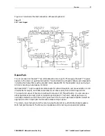
Figure 2-7 SLE*-* block diagram ................................................................................................................................................... 2-7
Figure 2-8 SLE*-* options and accessories................................................................................................................................ 2-10
Figure 3-1 Equalizer slope versus cable ...................................................................................................................................... 3-4
Figure 3-2 Frequency versus cable slope .................................................................................................................................... 3-6
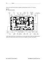
Figure 3-3 8LDR/*/III component layout (top-left, bottom-right)................................................................................................. 3-7
Figure 3-4 Typical flatness and control ranges ........................................................................................................................... 3-8
Figure 3-5 SLE-TDU cable selector ............................................................................................................................................. 3-10
Figure 3-6 SLE-ADU...................................................................................................................................................................... 3-11
Figure 3-7 SLE*-* fuses ................................................................................................................................................................ 3-14
Figure 4-1 Test equipment connections for bench sweeping.................................................................................................... 4-2
Figure 5-1 Center-conductor pin length ....................................................................................................................................... 5-1
Figure 5-2 Torque sequence.......................................................................................................................................................... 5-2
Tables
Table 2-1 SLE*-* options and accessories ................................................................................................................................... 2-8
Table 3-1 STARLINE Forward Equalizers – SFE*-* ...................................................................................................................... 3-3
Table 3-2 STARLINE cable simulators.......................................................................................................................................... 3-5
Table 3-3 Gain reserve versus ambient temperature .................................................................................................................. 3-9
Table 3-4 SLE-ADU pad levels ..................................................................................................................................................... 3-12