background image


PRELIMINARY - Motorola Internal Use Only 

SLE*-* Installation and Operation Manual 

Section 2 

Overview 

The SLE*-* is a two-way capable line extender used in CATV distribution systems. The SLE*-* 
is powered by the 60–90 VAC cable supply and can be configured to pass this power to 
additional line extenders. The standard model SLE*-* includes the amplifier with an integrated 
DC power supply and active return path for two-way signal flow.  

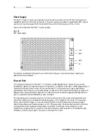
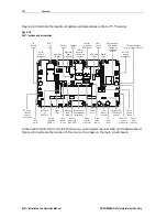
Figure 2-1 illustrates the base of the SLE*-*: 

Figure 2-1  
SLE*-* base 

C A U TION :  C ONTA IN S  PA RTS  A N D
A SSE M BL IES  SU S CE PTIB LE  TO
D A M AG E  B Y E LE C TR O STATIC
D IS C HA R GE   ( ESD )

CHECK VOLTAG E

SE LECTOR

REFER TO MANUAL

AC

TEST

POINT

RTN EQ

JXP IN

JXP OUT

LPF

LPF

ICS

DC

AC

POWER PORT

FUSE

FUSE 1

SP

ADJ
JXP

JXP MID

JXP IN

FUSE 2

+24 DC

TEST PORT

STATUS

MONITOR

STATUS

MONITOR

MAN

ADJ

ADJ

ADU

RCB87

FWD EQ

LDR BD

EATT

-20 dB

-20 dB

H

H

L

L

-20 dB

-20 dB

-16 dB

RF IN

0

0

0

0

0

0

0

RF OUT2

RF OUT1

REFER TO

MANUAL FO R

FUSE VA LUES

MGC

AUTO

R1

R2

R3

R4

C1

C2

C3

C6

C8

P1

P2

P4

P3


Содержание STARLINE SLE Series

Страница 1: ...Installation and Operation Manual SLE STARLINE Line Extender ...

Страница 2: ...en the equipment is operated in a commercial environment This equipment generates uses and can radiate radio frequency energy and if not installed and used in accordance with the Installation Manual may cause harmful interference to radio communications Operation of this equipment in a residential area is likely to cause harmful interference in which case the user will be required to correct the i...

Страница 3: ...ation on the part of Motorola to provide notification of such revision or change Motorola provides this guide without warranty of any kind either implied or expressed including but not limited to the implied warranties of merchantability and fitness for a particular purpose Motorola may make improvements or changes in the product s described in this manual at any time MOTOROLA the Stylized M Logo ...

Страница 4: ...ation 2 2 Housing 2 3 Gaskets 2 4 Port Locations 2 5 Power Supply 2 6 Forward Path 2 6 Return Path 2 7 Ingress Control Switch 2 8 Options and Accessories 2 8 Section 3 Amplifier Setup Forward Path Alignment 3 1 Before You Begin 3 1 Cable Equalizer 3 2 STARLINE Cable Simulators 3 5 Input and Midstage Pads 3 6 Flatness Control 3 6 Directional Coupler Test Points 3 8 SLE Bode Equalization 3 8 Amplifi...

Страница 5: ... Testing Return Gain and Response 4 4 Completing the Test Procedures 4 4 Section 5 Installation Aerial Installation 5 1 Pedestal Installation 5 3 Surface Mounting 5 3 Section 6 Operating Tips Using Amplifiers in Lower Frequency Systems 6 1 Using Amplifiers in Lower Gain Systems 6 1 Appendix A Specifications SLE A 1 AC Current A 2 Return Path A 2 SLE ADU A 2 Appendix B Torque Specifications Figures...

Страница 6: ...le slope 3 6 Figure 3 3 8LDR III component layout top left bottom right 3 7 Figure 3 4 Typical flatness and control ranges 3 8 Figure 3 5 SLE TDU cable selector 3 10 Figure 3 6 SLE ADU 3 11 Figure 3 7 SLE fuses 3 14 Figure 4 1 Test equipment connections for bench sweeping 4 2 Figure 5 1 Center conductor pin length 5 1 Figure 5 2 Torque sequence 5 2 Tables Table 2 1 SLE options and accessories 2 8 ...

Страница 7: ...urge requirements using surge waveforms as described in IEEE C62 41 Features of the SLE include 870 MHz power doubling technology in gallium arsenide GaAs Modular diplex filter splits Ease of use ergonomics 60 90 VAC line power option Thermal and auto controlled Bode equalization optional Second output option using SP splitter or DC coupler 20 dB directional coupler test points Optional return pat...

Страница 8: ... VOLTS ARE PRESENT UNDER COVER AND MAY BE PRESENT AFTER POWER IS REMOVED Base Lid CAUTION CONTAINS PARTS AND ASSE MBLIES SUSCEPTIBLE TO DAMAG E BY ELECTRO STATIC DIS CHARGE ESD CHECK VOLTAGE SELECTOR REFER TO MANUAL AC TEST POINT RTN EQ JXP IN JXP OUT LPF LPF ICS DC AC POWER PORT FUSE FUSE 1 SP ADJ JXP JXPMID JXPIN FUSE 2 24 DC TEST PORT STATUS MONITOR STATUS MONITOR MAN ADJ ADJ ADU RCB87 FWD EQ L...

Страница 9: ...ed in the SLE Abbreviations and Acronyms The Abbreviations and Acronyms list contains the full spelling of the short forms used in this manual This installation manual assumes that all channels are standard National Television Standards Committee NTSC analog channels Refer to catalog specifications for further details pertaining to signal levels of digital channels above 550 MHz This installation ...

Страница 10: ...g 24 hours per day 7 days per week http businessonline motorola com 888 944 4357 215 323 0044 888 944 HELP Data Networks Transmission Products PRESS 3 Products PRESS 1 Cable Router VOIP PRESS 2 Cable Modems Products PRESS 3 Transmission Transport Products MBT MWT MEA PRESS 5 Multiservice Management PRESS 4 Network Licensing PRESS 1 Network Management Products PRESS 2 Network Technical Response Cen...

Страница 11: ...d then call 52 631 311 1100 to contact the Repair Facility When shipping equipment for repair follow these steps 1 Pack the unit securely 2 Enclose a note describing the exact problem 3 Enclose a copy of the invoice that verifies the warranty status 4 Ship the unit PREPAID to the following address Motorola Inc Broadband Communications Sector c o Exel Attn RSA _________ 6908 East Century Park Drive...

Страница 12: ...return path for two way signal flow Figure 2 1 illustrates the base of the SLE Figure 2 1 SLE base CAUTION CONTAINS PARTS AND ASSE MBLIES SUS CE PTIBLE TO DAMAG E BY E LE CTRO STATIC DIS CHARGE ESD CHECK VOLTAGE SELECTOR REFER TO MANUAL AC TEST POINT RTN EQ JXP IN JXP OUT LPF LPF ICS DC AC POWER PORT FUSE FUSE 1 SP ADJ JXP JXPMID JXP IN FUSE 2 24 DC TEST PORT STATUS MONITOR STATUS MONITOR MAN ADJ ...

Страница 13: ...ped configuration is also noted on labels located on the side of the housing Please confirm the availability of frequency splits with your Motorola sales representative Figure 2 2 SLE configurator Key 87J 5 55 MHz 70 870 MHz 5 42 MHz 54 870 MHz 5 30 MHz 47 870 MHz 5 65 MHz 85 870 MHz 5 40 MHz 52 870 MHz 87K 87E 87A 87S Bandpass Split Key 19 dB Station Gain L X X H 8 dB Fmin 870 MHz E GaAs High Out...

Страница 14: ...housing and provides its dimensions Figure 2 3 SLE housing dimensions 10 75 inches 4 5 inches Coaxial cable connections to the housing are made using conventional 5 8 inch 24 threads per inch stinger type connectors For strand mounting use the two messenger clamps located on the side of the housing Figure 2 5 that are secured with 5 16 inch 24 threads per inch stainless steel bolts Use the L brack...

Страница 15: ... Housing gaskets INPUT VOLTAGE 30 95 VOLTSAC FREQ 50 60 Hz OUTPUT VOLTAGE 24 0 5 VOLTS DC CURRENT 1 5 AMPS DC CAUTION CONSULT INSTALLATION MANUAL PRIOR TO REMOVING PROTECTIVE COVER VOLTAGES IN EXCESS OF 300 VOLTS ARE PRESENT UNDER COVER AND MAY BE PRESENT AFTER POWER IS REMOVED CAUTION CONTAINS PARTS AND ASSE MBLIES S US CE PTIBLE TO DAMAG E BY E LE CTRO STATIC DIS CHARGE ESD CHECK VOLTAGE SELECTO...

Страница 16: ... output A fourth housing port provides access to the return path RF test point All ports are protected by factory inserted threaded plugs or plastic cap plugs Discard the plastic cap plugs when you install the cable connectors Figure 2 5 illustrates the housing port locations Figure 2 5 Housing ports Output port 1 Output port 2 Input port AC test point Return test point Messenger clamp bolts ...

Страница 17: ...ending on model with 16 dB of return loss If you use the SLE in a system that may require Bode equalization in the future you should install a 7 dB JXP at the JXP MID1 location Figure 2 7 between the input and output hybrid The 7 dB JXP ensures that the appropriate operational gain is used when the SLE BODE is later installed The operating gain includes provisions for the insertion loss of the inp...

Страница 18: ...board of the SLE accommodates the return path This equips the SLE to pass signals in the return or upstream direction The standard circuit board contains all components including the diplex filters with extended return bandwidth for the amplifier input and output All items are plug in and easily installed Optional SRE return equalizers compensate for cable attenuation and are available in 1 dB inc...

Страница 19: ...ropriately for the field location requirements You must install the correct forward equalizer or broadband cable simulator and input pad to place the unit into service Section 3 Amplifier Setup provides information to assist you in this task Use model JXP B pads to control field signal levels To compensate for temperature install the automatic drive unit SLE ADU or thermal drive unit SLE TDU befor...

Страница 20: ...es with temperature in the return path LL SLE HMS Status monitor module This module enables monitoring of the unit s operating parameters by the LIFELINE status monitoring system This accessory also requires the deep housing cover SLE LID SM Deep housing cover This optional cover is required to contain the LIFELINE status monitor module RCB87 Response Correction Board This optional board compensat...

Страница 21: ...LE AGC or SLE TDU Diplex filter Manual level MAN Drive control select jumper Man Auto Power port TP return input Optional ICS JXP jumper shown OUT 2 power block TP forward input TP return output seizure mechanism AC test point Input power block Return equalizer SRE Return output pad JXP OUT Status monitor connector From status monitor Return pad JXP IN Auto level ADU RF OUT 2 seizure mechanism SFE...

Страница 22: ...s For proper forward alignment obtain RF output levels and tilts of all SLE s in the forward or return path RF input level for the SLE being set up from system design or as built map A carrier at the system s highest frequency It can be modulated or continuous wave CW and should be inserted in the headend at standard video levels This carrier is used to simplify field set up It is recommended that...

Страница 23: ...cable Subtract this cable length from the 20 dB of this example 20 8 12 The SFE 87 12 is the proper equalizer in this case With this equalizer installed the SLE reproduces the output tilt of the last upstream amplifier When selecting an equalizer choose the next lower value if the exact value is not available or in cases where the calculated value makes two choices possible Example 2 The SLE is us...

Страница 24: ...ed value makes two choices possible Table 3 1 helps you choose the correct equalizers and also lists insertion loss at various frequencies Table 3 1 STARLINE Forward Equalizers SFE Frequency MHz versus Insertion Loss dB Equalizer Value Equalizer Slope 50 200 300 450 550 650 750 870 SFE 87 22 16 7 17 7 12 4 10 0 7 1 5 4 3 9 2 5 1 0 20 15 2 16 2 11 4 9 2 6 5 5 0 3 6 2 3 1 0 18 13 7 14 7 10 3 8 4 6 0...

Страница 25: ...le dB of Cable dB of Equalizer Slope 0 0 2 4 6 8 10 12 14 16 18 20 30 28 26 24 22 20 18 16 14 12 10 6 4 2 8 550 MHz 650 MHz 750 MHz 870 MHz Slope versus Cable When selecting an equalizer choose the next lower value if the exact value is not available or in cases where the calculated value makes two choices possible Because of errors in cable attenuation slope in passive devices and other independe...

Страница 26: ... in dB 40 MHz 0 0 0 1 0 1 0 1 0 2 0 2 0 3 0 3 0 3 0 4 45 MHz 0 0 0 0 0 1 0 1 0 1 0 1 0 1 0 1 0 2 0 2 50 MHz 0 0 0 0 0 0 0 0 0 0 0 0 0 0 0 0 0 0 0 0 72 MHz 0 1 0 2 0 2 0 3 0 4 0 4 0 5 0 6 0 7 0 7 108 MHz 0 1 0 3 0 4 0 5 0 6 0 8 0 9 1 0 1 2 1 3 150 MHz 0 2 0 5 0 7 0 9 1 2 1 4 1 6 1 9 2 1 2 3 211 MHz 0 3 0 7 1 0 1 4 1 7 2 1 2 4 2 8 3 1 3 5 250 MHz 0 4 0 8 1 2 1 7 2 1 2 5 2 9 3 3 3 7 4 1 300 MHz 0 5 1...

Страница 27: ...he 8LDR III circuit board includes flatness controls and a fixed cable equalizer for 870 MHz This equalizer plus the contribution of the hybrid gain stages produces approximately the dB of slope indicated by the model number 8 dB of tilt with an 8LDR 8 III or 12 dB of tilt with an 8LDR 12 III You can adjust the LDR variable resistors and capacitors to flatten the response across the operating band...

Страница 28: ...adjusts for maximum gain at Fmax 870 MHz C7 and R8 adjust for the flattest response in the mid to upper portion of the band C8 adjusts for the flattest response in the low to mid range of the band L4 on the bottom of the LDR board may slightly tune the upper portion of the response Excessive spreading of L4 will increase insertion loss Figure 3 3 illustrates the LDR III Figure 3 3 8LDR III compone...

Страница 29: ...nce they do not require special test probes After the output hybrid a second directional coupler provides signal to the optional SLE ADU board This signal is used only when the SLE ADU board is installed It is not necessary to terminate this port when the SLE ADU is not installed SLE Bode Equalization The optional SLE Bode board which is an electronically controlled equalizer receives its control ...

Страница 30: ...ive control select jumper is in the MAN position 3 Use a signal level meter to measure the high band edge carrier input level at the input test point 870 MHz channel 136 This carrier should be at standard analog level non scrambled 4 Verify that the input level agrees with the design specification input If the level is different from design adjust accordingly For example the design level is 19 dBm...

Страница 31: ...input pad by 1 dB For each decrease in SCS value increase the input pad by 1 dB If you replace an SFE with an SCS reduce the value of the input pad by the value of the SCS 8 Measure the output level at the highest frequency It should be within 1 dB of the system design level If it is not you must adjust the mid stage pad JXP MID accordingly Refer to Section 6 Operating Tips for mid stage padding i...

Страница 32: ...ble attenuation and hybrid output associated with a change in temperature The SLE Bode equalizer then changes its insertion loss to maintain a constant output level The SLE ADU illustrated in Figure 3 6 maintains the most precise output level of the three available methods Figure 3 6 SLE ADU AUTOMATIC DRIVE UNIT SLE ADU _______________ Pilot frequency To set up the SLE ADU 1 Position the drive con...

Страница 33: ...above 47 dBmV Pad Value above 49 dBmV ADU 0 dB N A 10 dB QADU 0 dB 6 dB N A Use of the SLE ADU or SLE TDU is recommended for improved output level stability although you can operate the SLE in the manual mode Select manual mode by placing the drive control select jumper illustrated in Figure 2 8 in the MAN position The gain of the SLE is then determined by the potentiometer marked MAN on the ampli...

Страница 34: ...er installed 5 If you ordered the optional ICS verify that the switch is installed in the ICS location If it was not ordered the factory installed jumper should remain in the ICS location 6 Verify that the return output pad socket JXP THERM located between the hybrid output and the SRE has a 0 dB pad or JXP ZX jumper or a JXP TH C installed 7 Set the sweep equipment output level to the amplifier s...

Страница 35: ... 7 illustrates the location of the fuses in the SLE Figure 3 7 SLE fuses F2 F1 Fuse CAUTION CONTAINS PARTS AND ASSE MBLIES S US CE PTIBLE TO DAMAG E BY E LE CTRO STATIC DIS CHARG E ESD CHECK VOLTAGE SELECTOR REFER TO MANUAL AC TEST POINT RTN EQ JXPIN JXPOUT LPF LPF ICS DC AC POWER PORT FUSE FUSE 1 SP ADJ JXP JXPMID JXPIN FUSE 2 24 DC TEST PORT STATUS MONITOR STATUS MONITOR MAN ADJ ADJ ADU RCB87 FW...

Страница 36: ...erly aligned on the bench only minor adjustments may be required in the field The following subsections provide instructions to bench align the SLE Before You Begin The SLE is shipped with a 20 ampere blade type fuse in the output port for over current protection CAUTION To avoid applying 60 90 VAC to the test equipment during testing remove the fuse illustrated in Figure 2 8 Open the housing and ...

Страница 37: ...uipment as shown in Figure 4 1 Figure 4 1 Test equipment connections for bench sweeping Network analyzer SLE under test Cable simulator Power combiner 117 VAC AC power supply 60 90 VAC Sweep input Sweep output CAUTION Before you begin the following subsection remove the input pad JXP IN to avoid damage to the hybrids before you apply power Measuring Forward Gain This subsection provides instructio...

Страница 38: ...e operational gain and flatness of the amplifier 1 Perform steps 1 through 6 in Measuring Forward Gain above 2 Estimate the ambient temperature and find the required gain reserve by referring to Table 3 3 Reduce the gain at the highest frequency by the amount given in the table Example The ambient temperature is 70 F The table indicates that the required gain reserve is 4 dB Reduce the gain by 4 d...

Страница 39: ... is flat Any tilt that is due to the return equalizer must average out to a flat response in a cascade of amplifiers A slope adjustment is not available in the return bandpass 4 Measure the gain at the maximum return band frequency 65 MHz for A split The amplifier gain is the sum of the measured gain the insertion loss of the return cable equalizer at the maximum return band frequency the insertio...

Страница 40: ...nter conductor seizure mechanism and degrade the match Extremely long pins can result in a short circuit Figure 5 1 Center conductor pin length 1 65 Max 1 50 Min To install the unit 1 Power down the cable before you install the housing This avoids blown fuses tripped circuit breakers and possible personal injury 2 Mount the housing and torque the two 5 16 inch messenger clamp bolts illustrated in ...

Страница 41: ...er screws 10 to 12 in lbs 11 Check the condition of the RF and weather gaskets and replace them if necessary If needed also apply a light coating of silicone grease 12 Close the housing and use a torque wrench to sequentially and progressively tighten the housing bolts to a final torque of 6 ft lb in the sequence specified on the housing cover and illustrated in Figure 5 2 Figure 5 2 Torque sequen...

Страница 42: ... compensation provided by the SLE TDU can be inaccurate and result in signal level changes with ambient temperature change One approach to this problem is to select the least amount of cable setting low on the SLE TDU This results in minimal gain change with temperature A preferred approach is to install a JXP TH C thermal attenuator while operating the SLE in the manual mode To mount the SLE on a...

Страница 43: ...best choice even in an 870 MHz amplifier Note also that the equalizer cuts off at the frequency value for which it is designed For example an SFE 75 cuts off frequencies above 750 MHz Therefore if you have an 870 MHz system and need the equalizer to perform to 870 MHz you must use an SFE 87 Using Amplifiers in Lower Gain Systems There are two pad facilities in the forward path 1 the pad location J...

Страница 44: ...perational 28 32 dB minimum full gain with SFE and slope reserves with SLE Bode Flatness 52 870 MHz 1 dB maximum Level control automatic SLE Bode board using SLE ADU TDU Gain control Fixed pads JXP B Performance reference frequency MHz 870 550 52 At typical output dBmV 43 44 37 Channels 79 analog 320 MHz digital suppressed by 6 dB Crossmod worst case 63 dB CTB worst case 74 dB CSO worst case 74 dB...

Страница 45: ...ss 0 50 dB maximum Level control Fixed pads JXP B input and output Performance At typical output 41 dBmV flat Channels 4 NTSC Crossmod worst case 74 dB Single triple beat worst case 82 dB Single second order worst case 77 dB Noise figure 6 dB Power requirements 24 VDC 125 mA SLE ADU Parameter Specification Pilot channel See current catalog Adjacent channel frequency 6 MHz Minimum BLE output at pil...

Страница 46: ...lbs Ft lbs N M Strand clamp pedestal mounting 5 16 18 1 2 inch 120 144 10 12 13 6 16 3 Housing lid closure 1 4 20 7 16 inch 72 6 0 8 1 Test point plugs 5 8 24 1 2 inch 25 40 2 1 3 3 2 8 4 5 Seizure screw 8 32 3 16 inch or Phillips 12 1 0 1 4 Hybrid 6 32 Phillips 10 12 0 8 1 0 1 1 1 4 Chassis cover 6 32 1 4 inch or Phillips 10 12 0 8 1 0 1 1 1 4 Status monitor 10 32 triple lead 5 16 inch 24 30 2 0 ...

Страница 47: ... noise CSO Composite Second Order CTB Composite Triple Beat cw Continuous wave dB Decibel dBmV Decibels referenced to one millivolt E GaAs Enhanced Gallium Arsenide ICS Ingress Control Switch MHz Megahertz NTSC National Television Standards Committee rms root mean square RSA Return for Service Authorization SAW Surface Acoustic Wave SCS Starline Cable Simulator SFE Starline Forward Equalizer SRE S...

Страница 48: ...MGBI 509836 001 11 04 Visit our website at www motorola com ...

Отзывы: