


Amplifier
Setup
3-7
PRELIMINARY - Motorola Internal Use Only
SLE*-* Installation and Operation Manual
!
C3 produces a peak that is centered approximately 300 MHz above the lowest forward
frequency and varied in amplitude by R3. This adjustment provides more mid-band
alignment flexibility.
!
C6 adjusts for maximum gain at Fmax (870 MHz).
!
C7 and R8 adjust for the flattest response in the mid- to upper portion of the band.
!
C8 adjusts for the flattest response in the low to mid-range of the band.
L4, on the bottom of the LDR board, may slightly tune the upper portion of the response.
Excessive spreading of L4 will increase insertion loss.
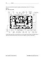
Figure 3-3 illustrates the LDR/*/III:
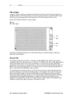
Figure 3-3
8LDR/*/III component layout (top-left, bottom-right)
R1
R2
R3
R8
C8
C1
C2
C3
C7
C6
P1
P2
P4
P3
L4
L6
L5
L7


