Disassembly/Reassembly Procedures
: Pager Reassembly – Detailed
4-9
4.4
Pager Reassembly – Detailed
4.4.1
Front Housing Reassembly
4.4.1.1 Reset Button Reasassembly
Follow the reverse of Section 4.3.2.5 "Reset Button Disassembly" on page 4-8.
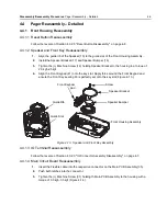
4.4.1.2 Speaker and Front Key Reasassembly
1.
Align the guide rib of the Speaker (15) to the guide slot of the Front Housing Assembly.
2.
Install the Speaker Bracket (17) and Speaker Bumper (16).
3.
Tighten the (+) Machine Screw (18) holding Speaker Bracket to the housing to a torque of
2.0 kgf~2.5kgf.
4.
Align the Front Keypad (41) onto the key slot. Apply force around the Front Keypad and
ensure the Front Key sealing rib is perfectly set onto the key slot (Figure 4-13.).
.
Figure 4-13. Speaker and Front Key Assembly
4.4.1.3 IO Terminal Reasassembly
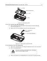
Follow the reverse of Section 4.3.2.3 "IO Connector Assembly Disassembly" on page 4-7.
4.4.1.4 Main Circuit Board Reasassembly
1.
Insert the Flexible cable into the respective connector on the Main PCB Assembly (35).
2.
Push both latches into the connector.
3.
Tighten the (+) Machine Screw (31) holding th Main PCB Assembly to the housing with a
torque of 3.0 kgf~3.5 kgf (Figure 4-14.).
Screw
Speaker Bracket
Speaker Bumper
Front Housing Assembly
Front Keypad-
pad
Guide Rib
Guide Slot
Содержание MINITOR VI
Страница 1: ...MINITOR VI SELECTIVE CALL ALERT MONITOR RECEIVER BASIC SERVICE MANUAL ...
Страница 46: ...Notes 5 2 Accessories Introduction ...
Страница 48: ...Notes A 2 Replacement Parts Kits Accessories and Aftermarket Division AAD ...
Страница 49: ......


