background image

Chapter 1 Introduction

1.1

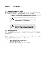
Notations Used in This Manual

Throughout the text in this publication, you will notice the use of note and caution notations. These notations 
are used to emphasize that safety hazards exist, and due care must be taken and observed.

1.2

Pager Description

The Motorola MINITOR VI pager is an easy-to-use, compact alert monitor, powered by rechargeable Li-ion 
and/ or Alkaline batteries (for non-Intrinsically Safe models only). The pager can operate on selected UHF and 
VHF frequencies.

The MINITOR VI pager uses the most advanced self-contained, sealed, and custom-integrated circuits to 
perform the complex functions involved in radio paging. The pager is housed in a high-impact resistant case 
that offers excellent protection against dust intrusion, vibration, and shock. Lightweight and small in size, the 
unit can be carried comfortably in a pocket or purse, or clipped onto a belt.

The pager offers the following models:

• Single Channel Stored Voice (Intrinsically Safe (IS))
• Five Channel Stored Voice (IS)
• Single Channel Stored Voice (non-Intrinsically Safe (non-IS))
• Five Channel Stored Voice (non-IS)

The MINITOR VI pager is available in various frequency ranges. See “

Summary of Bands Available

” on 

page 1-3

 for Radio Frequency Ranges.

NOTE

An operational procedure, practice, or condition that is essential to emphasize.

CAUTION indicates a potentially hazardous situation which, if 
not avoided, might result in equipment damage.

WARNING indicates a potentially hazardous situation 
which, if not avoided, could result in death or injury.

!

C a u t i o n

!

W A R N I N G

!

Содержание MINITOR VI

Страница 1: ...MINITOR VI SELECTIVE CALL ALERT MONITOR RECEIVER BASIC SERVICE MANUAL ...

Страница 2: ...operation of law in the sale of a product Document Copyrights No duplication or distribution of this document or any portion thereof shall take place without the express written permission of Motorola No part of this manual may be reproduced distributed or transmitted in any form or by any means electronic or mechanical for any purpose without the express written permission of Motorola Disclaimer ...

Страница 3: ...iii Document History The following major changes have been implemented in this manual since the previous edition Edition Description Date 68009688001 A Initial Release Oct 2014 ...

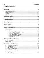
Страница 4: ...x II General Provisions ix III State Law Rights Applicable Only in U S A x IV How To Get Warranty Service x V What This Warranty Does Not Cover x VI Patent And Software Provisions xi VII Governing Law xi Battery and Charger Warranty xii Workmanship Warranty xii Capacity Warranty xii Chapter 1 Introduction 1 1 1 1 Notations Used in This Manual 1 1 1 2 Pager Description 1 1 1 2 1 MINITOR VI 1 2 1 3 ...

Страница 5: ...sembly 4 5 4 3 2 1 Switch PCB Asssembly Disassembly 4 5 4 3 2 2 Main Circuit Board Disassembly 4 6 4 3 2 3 IO Connector Assembly Disassembly 4 7 4 3 2 4 Speaker Front Key Disassembly 4 7 4 3 2 5 Reset Button Disassembly 4 8 4 4 Pager Reassembly Detailed 4 9 4 4 1 Front Housing Reassembly 4 9 4 4 1 1 Reset Button Reasassembly 4 9 4 4 1 2 Speaker and Front Key Reasassembly 4 9 4 4 1 3 IO Terminal Re...

Страница 6: ...vi Table of Contents 5 1 4 Programming 5 1 Appendix A Replacement Parts Kits A 1 A 1 Level 1 and 2 Maintenance A 1 A 1 1 Replacement Parts Ordering A 1 A 2 Accessories and Aftermarket Division AAD A 1 ...

Страница 7: ... 4 5 Figure 4 7 Removing Knobs 4 6 Figure 4 8 Removing Switch PCB Assembly 4 6 Figure 4 9 Removing Main PCB 4 7 Figure 4 10 Removing IO Connector Assembly 4 7 Figure 4 11 Removing Speaker and Front Key 4 8 Figure 4 12 Removing Reset Button 4 8 Figure 4 13 Speaker and Front Key Assembly 4 9 Figure 4 14 Main PCB Assembly 4 10 Figure 4 15 Assembling Switch PCB Assembly 4 10 Figure 4 16 Thread of Swit...

Страница 8: ... Tables Table 2 1 Recommended Test Equipment 2 1 Table 2 2 Service Aids 2 2 Table 3 1 Initial Equipment Control Settings 3 3 Table 4 1 MINITOR VI Exploded View Parts List 4 15 Related Publications MINITOR VI User Guide 6800969001 ...

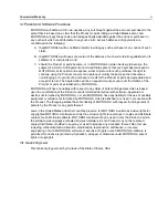
Страница 9: ...een MOTOROLA and the original end user purchaser MOTOROLA does not warrant the installation maintenance or service of the Product MOTOROLA cannot be responsible in any way for any ancillary equipment not furnished by MOTOROLA which is attached to or used in connection with the Product or for operation of the Product with any ancillary equipment and all such equipment is expressly excluded from thi...

Страница 10: ...cts or damage from misuse accident water or neglect C Defects or damage from improper testing operation maintenance installation alteration modification or adjustment D Breakage or damage to antennas unless caused directly by defects in material workmanship E A Product subjected to unauthorized Product modifications disassemblies or repairs including without limitation the addition to the Product ...

Страница 11: ...f the Product or parts as established by MOTOROLA MOTOROLA will have no liability with respect to any claim of patent infringement which is based upon the combination of the Product or parts furnished hereunder with software apparatus or devices not furnished by MOTOROLA nor will MOTOROLA have any liability for the use of ancillary equipment or software not furnished by MOTOROLA which is attached ...

Страница 12: ...kmanship warranty guarantees against defects in workmanship under normal use and service Capacity Warranty The capacity warranty guarantees 80 of the rated capacity for the warranty duration Lithium Ion Li lon Batteries One 1 Years Chargers Two 2 Years Lithium Ion Li lon Batteries 12 Months ...

Страница 13: ...n a high impact resistant case that offers excellent protection against dust intrusion vibration and shock Lightweight and small in size the unit can be carried comfortably in a pocket or purse or clipped onto a belt The pager offers the following models Single Channel Stored Voice Intrinsically Safe IS Five Channel Stored Voice IS Single Channel Stored Voice non Intrinsically Safe non IS Five Cha...

Страница 14: ...attery level is high Solid Yellow indicates battery level is medium Solid Red indicates battery level is low Blinking Red indicates battery level is critically low RESET BUTTON TURN OFF audio alert battery status indicators FUNCTION SELECTOR KNOB Rotate clockwise and counter clockwise to select preprogram function modes PLAY BUTTON Play message stored in memory NEXT FASTFORWARD BUTTON Skip to next...

Страница 15: ...del Charts 1 4 1 VHF Tanapa Chart Frequency Band Bandwidth VHF 143 174 MHz UHF 406 430 450 486 476 512 MHz Model Number Tanapa Description A03JAC8JA2AN RLD1047_ 143 174 MHZ SGL CH NON IS MINITOR VI PAGER A03JAC8JA1AN RLD1048_ 143 174 MHZ SGL CH IS MINITOR VI PAGER A03JAC9JA2AN RLD1049_ 143 174 MHZ FIVE CH NON IS MINITOR VI PAGER A03JAC9JA1AN RLD1050_ 143 174 MHZ FIVE CH IS MINITOR VI PAGER ...

Страница 16: ...MINITOR VI PAGER A04RAC8JA2AN RLE1121_ 450 486 MHZ SGL CH NON IS MINITOR VI PAGER A04RAC8JA1AN RLE1120_ 450 486 MHZ SGL CH IS MINITOR VI PAGER A04RAC9JA2AN RLE1119_ 450 486 MHZ FIVE CH NON IS MINITOR VI PAGER A04RAC9JA1AN RLE1118_ 450 486 MHZ FIVE CH IS MINITOR VI PAGER A04SAC8JA2AN RLE1117_ 476 512 MHZ SGL CH NON IS MINITOR VI PAGER A04SAC8JA1AN RLE1116_ 476 512 MHZ SGL CH IS MINITOR VI PAGER A04...

Страница 17: ...y typ 4 5 μV m 12 5kHz On Body max 4 5 μV m 25kHz On Body max 5 5 μV m 12 5kHz Free Field 10 0 μV m 8 position avg 13 0 μV m on body Selectivity 65 dB TIA603 D Spurious Image 70 dB TIA603 D Intermodulation 65 dB TIA603 D Spurious Emissions all bands Conducted 55 dB TIA603 D Radiated 55 dB TIA603 D Co channel rejection 8 dB First Oscillator Stability 10 ppm High level blocking 84 dB ETSI 90 dB Moto...

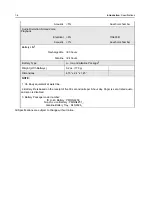
Страница 18: ...geable 80 hours Alkaline 24 hours Battery Type Li Ion and Alkaline Package3 Weight With Batterys 6 2 oz 176 g Dimensions 4 15 x 2 4 x 1 45 NOTE 1 On Body equivalent at waist line 2 Battery life is based on the receipt of five 30 second calls per 8 hour day Pager is set at rated audio and scan is disabled 3 Battery Package model number IS Li ion Battery PMNN4438_ Non IS Li ion Battery PMNN4451_ Alk...

Страница 19: ...Spacing 12 5 kHz 25 kHz per frequency Programmable feature Max Freq Separation UHF1 UHF2 UHF3 24 MHz 36 MHz 36 MHz Sensitivity Alerting On body1 On Body typ 3 0 μV m 25kHz On Body typ 4 0 μV m 12 5kHz On Body max 4 0 μV m 25kHz On Body max 5 0 μV m 12 5kHz Free Field 12 0 μV m 8 position avg 14 0 μV m on body Selectivity 65 dB TIA603 D Spurious Image 70 dB TIA603 D Intermodulation 65 dB TIA603 D S...

Страница 20: ...lectrical 6 TIA603 D Acoustic 7 Anechoic chamber Battery Life2 Rechargeable 80 hours Alkaline 24 hours Battery Type Li Ion and Alkaline Package3 Weight With Batterys 6 2 oz 176 g Dimensions 4 15 x 2 4 x 1 45 NOTE 1 On Body equivalent at waist line 2 Battery life is based on the receipt of five 30 second calls per 8 hour day Pager is set at rated audio and scan is disabled 3 Battery Package model n...

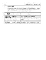
Страница 21: ...of equipment contained in Table 2 1 includes most of the standard test equipment required for servicing MINITOR VI Use equivalent whenever possible Table 2 1 Recommended Test Equipment Equipment Example Application RF Communications Test Set HP8920 or equivalent Tone Sensitivity test ...

Страница 22: ...any equivalent item capable of the same performance may be substituted for the item listed Table 2 2 Service Aids Motorola Part No Description Application TC 5062_ from TESCOM Co Ltd TEM CELL Provide RF isolation for Tone sensitivity test 6686119B01 Pry Opener Separate Back Housing Assembly from Front Housing Assembly PMDN4038_R Knob Opener Remove knobs PMDN4039_R Crab Eye Nut Opener Remove the nu...

Страница 23: ...r manufacturing process by utilizing high accuracy laboratory quality test equipment The recommended field service equipment approaches the accuracy of the manufacturing equipment with few exceptions This accuracy must be maintained in compliance with the manufacturer s recommended calibration schedule ...

Страница 24: ...amplitude of the signal generator according to a known signal 4 In this state the HP8920 or equivalent equipment should be set up as follows a QC2 signal should be sent to the pager by clicking Send and make sure that the Alert tone is OK b Repeat step 4a lowering the amplitude each time until 4 out of 5 Alerts are received Figure 3 1 Tone Sense Check Setup NOTE Tone Sensitivity results may vary b...

Страница 25: ... 1 Set RF Gen Freq as pager RX frequency 2 Set AF Gen2 TO 1 5 kHz for 12 5 kHz Channel Spacing 3 kHz for 25 kHz Channel Spacing 3 Push Send in AFGen2 Freq to send QC2 tones to pager 4 If pager decoded QC2 signal it will sound an Alert tone Table 3 1 Initial Equipment Control Settings Seq Num ON Time ms OFF Time ms Sym Freq Hz Amptd 1 1000 0 0 0 0 0 100 0 2 3000 0 0 1 288 5 100 0 3 33 0 0 0 2 2468 ...

Страница 26: ... the Reset Button 4 Press the Reset Button the red LED turns off and the amber LED turns on 5 Press the Reset Button the amber LED turns off and the Battery Indicator LED turns on red 6 Press the Reset Button the Battery Indicator LED turns green 7 Press the Reset Button all LEDs turn on the Battery Indicator LED is amber 8 Press the Reset Button all LEDs turn off and unit enters Pulsed Vibrate Mo...

Страница 27: ...ener PMDN4039_R Grease 1180369B40 TORX T6 and screwdriver If a unit requires further testing or service than is customarily performed at the basic level please send the radio to a Motorola Service Center listed in Appendix A 4 2 Maintenance The procedures in this section provide instructions for the disassembly of the MINITOR VI pager This product contains static sensitive devices Use anti static ...

Страница 28: ... out Figure 4 1 Removing Belt Clip 4 3 1 2 Removing Back Housing 1 Turn the pager off 2 Unlock the battery latch Once the front housing and back cover are disassembled the IS Intrinsic Safety Rating is voided Any warranty or repair work must be done by a IS approved repair facility The unit must be resealed during re assembly in order for the unit to maintain the IS Intrinsic Safety Rating for Haz...

Страница 29: ... Disassembly Detailed 4 3 Figure 4 2 Unlocking Battery Latch 3 Remove the battery pack Figure 4 3 Removing Battery 4 Remove the four protective rubber caps 32 33 34 from the Back Housing 5 Remove the four screws 31 with a TORX T6 screwdriver ...

Страница 30: ...Figure 4 4 Removing Screws and Protective Rubber Caps from Back Housing 6 Separate Back Housing Assembly from Front Housing Assembly with the Pry Opener Figure 4 5 Figure 4 5 Seperate Back Housing Assembly from Front Housing Assembly Protective rubber caps Pry Opener ...

Страница 31: ...3 2 1 Switch PCB Asssembly Disassembly 1 Remove the Volume Knob Kit 38 39 and Channel Knob Kit 36 37 from their shafts using the Chassis Opener 2 Remove the nuts from the Volume and Channel switch with the Crab Eye Nut Opener Figure 4 7 Be careful not to damage the terminals of the Vibrator 40 and ventilation felt when removing the vibrator C a u t i o n Vibrator 40 Ventilation Felt Terminal Vibra...

Страница 32: ... the Main PCB Assembly Figure 4 8 Figure 4 8 Removing Switch PCB Assembly 4 3 2 2 Main Circuit Board Disassembly 1 Remove the Machine Screw 31 holding the Main PCB Assembly 35 with a TORX T6 screwdriver 2 Pull the latch on the Main PCB Assembly to release the Flex from the connector and remove the Main PCB Assembly Figure 4 9 Volume Knob Kit Nut Channel Knob Kit Switch PCB Assembly Main PCB Assemb...

Страница 33: ...e Front Housing Assembly Figure 4 10 Removing IO Connector Assembly 4 3 2 4 Speaker Front Key Disassembly 1 Remove the Machine Screw 18 holding the Speaker Bracket 17 with a screwdriver 2 Remove the Speaker Bracket 3 Remove the Speaker 15 and Speaker Bumper 16 from the Front Housing Assembly Be careful not to damage the spring terminals of the speaker when removing the speaker bracket Screw Main P...

Страница 34: ...peaker and Front Key 4 3 2 5 Reset Button Disassembly 1 Remove the Bracket Reset button 7 2 Remove the Insulation Sheet 6 and Reset button 5 Figure 4 12 Figure 4 12 Removing Reset Button Screw Speaker Bracket Speaker Bumper Front Housing Assembly Front Keypad Bracket Reset button Reset button Front Housing Assembly Insulation Sheet ...

Страница 35: ...2 5kgf 4 Align the Front Keypad 41 onto the key slot Apply force around the Front Keypad and ensure the Front Key sealing rib is perfectly set onto the key slot Figure 4 13 Figure 4 13 Speaker and Front Key Assembly 4 4 1 3 IO Terminal Reasassembly Follow the reverse of Section 4 3 2 3 IO Connector Assembly Disassembly on page 4 7 4 4 1 4 Main Circuit Board Reasassembly 1 Insert the Flexible cable...

Страница 36: ...or Figure 4 15 Assembling Switch PCB Assembly 3 Apply the Screw fastener 3bond TB1410B around the thread of both Channel Volume switches Figure 4 16 4 Tighten the Nut for Ch Vol 24 holding the Channel Volume switches to the housing with Crab Eye Nut Tool torque to 4 0 kgf 5 0 kgf 5 Assemble the Volume Knob Kit 38 39 and Channel Knob Kit 36 37 Figure 4 17 Screw Main PCB Assembly Latch Flex Connecto...

Страница 37: ...mbling Knobs 4 4 2 Pager Reassembly 4 4 2 1 Back Housing Reasassembly Follow the reverse of Section 4 3 1 3 Back Housing Disassembly on page 4 5 4 4 2 2 Front Housing and Back Housing Reasassembly 1 Apply grease at the corners of the sealing area Figure 4 18 Thread of Switches Volume Knob Kit Nut Channel Knob Kit ...

Страница 38: ... not reuse original screws or screw caps The thread lock on the screws is degraded after removing and the caps may have been damaged when removed 3 Tighten the Machine Screw 31 with a TORX T6 screwdriver torque to 3 0 kgf 3 5 kgf 4 Assemble the Rubber Cap Small 34 Rubber Cap_R 32 and Rubber Cap_L 33 Figure 4 19 Be careful not to pinch the Battery Contact Sealing Rubber Grease Grease C a u t i o n ...

Страница 39: ... Pager Reassembly Detailed 4 13 Figure 4 19 Assembling the Back Housing Kit to the Front Housing Kit NOTE Ensure the Left and Right Rubber Caps are not reversed Rubber Cap Small Rubber Cap_R Rubber Cap_L Screws Terminal Sealing Rubber ...

Страница 40: ...and Parts Lists 4 5 Pager Exploded Mechanical View and Parts Lists 4 5 1 MINITOR VI Exploded View and Parts List Figure 4 20 MINITOR VI Exploded View 1 2 3 4 5 6 7 41 21 20 37 36 38 39 24 23 42 33 32 13 12 34 31 11 43 44 22 19 40 14 35 18 17 16 15 8 9 10 25 27 29 30 26 28 ...

Страница 41: ...pe Batt 4 1 Reset button 5 1 Insulation Sheet 6 1 Bracket Reset button 7 1 Felt SPK 8 1 Insert Screw 1 9 5 Insert Screw 2 10 1 RHN1007_ BACK HOUSING KIT Back Housing 11 1 Connector Cap 12 1 Sealing Batt Terminal 13 1 Ventilation Felt 14 1 RSN4006_ REPAIR KIT SPEAKER Speaker 15 1 Speaker Bumper 16 1 Speaker Bracket 17 1 Machine Screw for Speaker 18 1 RLN6518_ SWITCH KIT SWITCH VOL CHN Switch Volume...

Страница 42: ...TOR IO Flexible PCB 25 1 Housing IO 26 1 Pin Terminal 27 15 Sealing IO 28 1 Bracket IO 29 1 Bumper IO 30 2 RLN6520_ SCREW KIT Machine Screw 31 5 Rubber Cap_R 32 1 Rubber Cap_L 33 1 Rubber Cap Small 34 2 Connector Cap 12 1 Table 4 1 MINITOR VI Exploded View Parts List Continued Part Number Description Part Description Item No Quantity ...

Страница 43: ... UHF1 Non IS Five RLE1123_ RLN6532_ PCB Ass y UHF2 IS Single Channel PCB UHF2 IS SGL RLE1120_ RLN6533_ PCB Ass y UHF2 Non IS Single Channel PCB UHF2 Non IS SGL RLE1121_ RLN6534_ PCB Ass y UHF2 IS Five Channel PCB UHF2 IS Five RLE1118_ RLN6535_ PCB Ass y UHF2 Non IS Five Channel PCB UHF2 Non IS Five RLE1119_ RLN6536_ PCB Ass y UHF3 IS Single Channel PCB UHF3 IS SGL RLE1116_ RLN6537_ PCB Ass y UHF3 ...

Страница 44: ...MINITOR VI BELT CLIP Belt Clip 42 1 PMNN4438_ LI ION Battery Pack IS IS Li Ion 43 1 PMNN4451_ LI ION Battery Pack Non IS Non IS Li ion LB000117A01 IS Label MINITOR VI IS Label Motorola Repair Center only 44 1 LB000118A01 Non IS Label MINITOR VI Non IS Label Table 4 1 MINITOR VI Exploded View Parts List Continued Part Number Description Part Description Item No Quantity ...

Страница 45: ...ery Std IP56 Li Ion Non IS RLN6526_ MINITOR VI Alkaline Battery Tray Part No Description 25009298001 Standard Charger Power Supply 5V EPNN9288_ Amplified Charger Power Supply RLN6505_ Standard Charger Kit RLN6506_ Amplified Charger Kit RLN6507_ Amplified Charger Antenna VHF 143 174 MHz RLN6508_ Amplified Charger Antenna UHF 406 512 MHz Part No Description PMLN6725_ MINITOR VI Nylon Carry Case Plai...

Страница 46: ...Notes 5 2 Accessories Introduction ...

Страница 47: ...odule major mechanical parts are within Subscriber Product s specifications as per the service manual It does not incorporate discrete component replacement A 1 1 Replacement Parts Ordering When ordering replacement parts or equipment include the Motorola part number and description used in the service manual or supplement When ordering crystals or channel elements specify the Motorola part number...

Страница 48: ...Notes A 2 Replacement Parts Kits Accessories and Aftermarket Division AAD ...

Страница 49: ......

Страница 50: ...OTOROLA SOLUTIONS and the Stylized M logo are trademarks or registered trademarks of Motorola Trademark Holdings LLC and are used under license All other trademarks are the property of their respective owners 2014 Motorola Solutions Inc All rights reserved November 2014 68009688001 68009688001 A ...

Отзывы: