


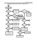


Troubleshooting Flow Chart for 25W Transmitter (Sheet 1 of 3)
3-3
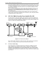
2.0
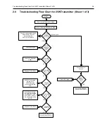
Troubleshooting Flow Chart for 25W Transmitter (Sheet 1 of 3)
Current
increase
when keyed?
NO
YES
START
Check if Pressure Pad closes S3440
Check Components between
Q3441 and RF Output,
Antenna Switch
D3471,D3472,Q3472
>500mA & <4A
>4A
<500mA
Check PA Stages
Control
Voltage at
TP3402
>1V
Short TP3403 to
Ground
NO
YES
Voltage at
TP3402
rises?
Check PA Stages
NO
YES
PCIC U3501
Pin 14 9.3V
DC?
Check 9.3 V Regulator
U0641
NO
YES
PCIC U3501
Pin 16 >4V
DC
Replace PCIC U3501
NO
YES
TP3404
9.1V DC
If U3201 Pin 2 is high,
replace PCIC
U3501,otherwise
check controller and
FGU
YES
NO
TP3403
>0.5V DC?
Replace PCIC U3501
Check Forward Power
Sense Circuit (D3451)
Check Forward Power
Sense Circuit (D3451)
NO
YES
PCIC U3501
Pin 5 > 1V
DC?
Check Power Setting,
Tuning & Components
between PCIC Pin 5
and ASFIC (U0221)
Pin 4 before replacing
ASFIC
No or too low Power when keyed
Содержание GM Series
Страница 1: ...Professional Radio GM Series VHF 136 174MHz Service Information Issue September 2000 ...
Страница 10: ...1 6 MODEL CHART AND TECHNICAL SPECIFICATIONS ...
Страница 22: ...2 12 THEORY OF OPERATION ...
Страница 32: ...3 10 TROUBLESHOOTING CHARTS ...


