


Chapter 2
THEORY OF OPERATION
1.0
Introduction
This Chapter provides a detailed theory of operation for the VHF circuits in the radio. For details of
the theory of operation and trouble shooting for the the associated Controller circuits refer to the
Controller Section of this manual.
2.0
VHF (136-174MHz) Receiver
2.1
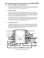
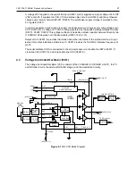
Receiver Front-End
The receiver is able to cover the VHF range from 136 to 174 MHz. It consists of four major blocks:
front-end bandpass filters and pre-amplifier, first mixer, high-IF, low-IF and receiver back-end. Two
varactor-tuned bandpass filters perform antenna signal pre-selection. A cross over quad diode mixer
converts the signal to the first IF of 44.85 MHz. High-side first injection is used.
Figure 2-1 VHF Receiver Block Diagram
Demodulator
1. Crystal
Filter
Mixer
Varactor
Tuned Filter
RF Amp
Varactor
Tuned Filter
Antenna
Control Voltage
from PCIC
First LO
from FGU
Recovered Audio
RSSI
IF
Second LO
2. Crystal
Filter
455kHz Filter
(25kHz)
455kHz Filter
(25kHz)
455kHz Filter
(12.5kHz)
455kHz Filter
(12.5kHz)
Switch
Switch
Switch
Switch
Limiter
1. IF Amp
2. IF Amp
Filter Bank Selection
from Synthesizer IC
Pin Diode
Antenna
Switch
RF Jack
Harmonic
Filter
Содержание GM Series
Страница 1: ...Professional Radio GM Series VHF 136 174MHz Service Information Issue September 2000 ...
Страница 10: ...1 6 MODEL CHART AND TECHNICAL SPECIFICATIONS ...
Страница 22: ...2 12 THEORY OF OPERATION ...
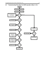
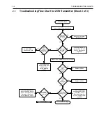
Страница 32: ...3 10 TROUBLESHOOTING CHARTS ...


