Peripheral Connectors
Technical Summary
2-27
2.22.1 Port B Expansion Connector
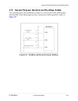
Port B is a GPIO port which is connected to the Port B header. The pins of the port,
PB0-PB7, are dedicated to general purpose I/O and Interrupt operations. The GPIO port
pins may be programmed as inputs, outputs or level-sensitive interrupt inputs.
shows the port pin to headed connections.
Table 2-12. Port B Connector Description
2.22.2 Port D Expansion Connector
Port D is an MPIO port with signal lines attached to various headers. The six pins of the
port, PD0-PD5, are dedicated to general purpose operation. The remaining two pins, PD6
and PD7, are shared with the TXD1 and RXD1 signal lines. The GPIO port pins may be
programmed as inputs, outputs or level-sensitive interrupt inputs.
shows the
exclusive Port D signals. The shared Port D signals are contained in
.
J20
Pin #
Signal
Pin #
Signal
1
PB0
2
PB1
3
PB2
4
PB3
5
PB4
6
PB5
7
PB6
8
PB7
9
GND
10
+3.3V
Table 2-13. Port D Connector Description
J23
Pin #
Signal
Pin #
Signal
1
PD0
2
PD1
3
PD2
4
PD3
5
PD4
6
PD5
7
GND
8
+3.3V
Содержание Digital DNA DSP56F807
Страница 2: ......
Страница 12: ...xii DSP56F807EVM Hardware User s Manual ...
Страница 53: ... DSP56F807EVM Schematics A 1 Appendix A DSP56F807EVM Schematics ...
Страница 72: ...A 20 DSP56F807EVM Hardware User s Manual ...
Страница 79: ......


