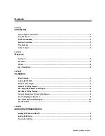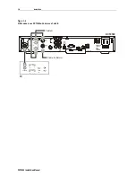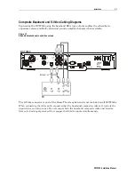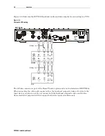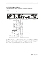
Overview 2-3
DCT2500 Installation Manual
Key Item Function
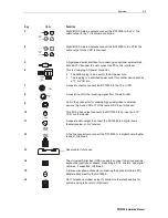
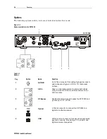
3
AUDIO
OUT
R
TO TV
TO VCR
L
Right/left RCA stereo outputs connect the DCT2500 to the TV. The
audio output to the TV is volume controlled.
4
AUDIO
OUT
R
TO TV
TO VCR
L
Right/left RCA stereo outputs connect the DCT2500 to the VCR. The
audio output to the VCR is line level.
5
DATA
A high-speed serial interface for connecting an optional external high
definition TV decoder (do not connect the PC to this interface)
6
SWITCHED
105-125V
60Hz
4A MAX
500W MAX
This is a two-plug AC power connector:
!
The bottom plug is an input for the AC power cord
!
The top plug is a switched power outlet for another device such as
a TV or VCR into
7
TO
TV/VC R
A coaxial output to connect the DCT2500 to the TV or VCR.
8
CABLE
IN
A coaxial input for the incoming signal from the wall outlet.
9
S-VIDEO
An S-Video connector for sending high quality video to external
devices (high-end VCR or TV) that accept S-Video. (Optional)
10
VIDEO
This RCA video output connects the DCT2500 to an input on a TV,
VCR, or other device.
11
DIGITAL
AUDIO
COAX
A coaxial audio output to connect the DCT2500 to a digital home
theater receiver or A/V receiver.
12
DIGITAL
AUDIO
OPTICAL
A Toslink connector to connect the DCT2500 to a digital home theater
receiver. (Optional)
13
TV PASS CA
Reserved for future use
14
USB
The Universal Serial Bus (USB) is used to connect to devices such as
keyboards, joysticks, scanners, disk storage, PCs, printers, and digital
cameras, if supported. (Optional)
15
IR
A stereo mini-phone connector connecting the optional Infrared (IR)
Blaster attachment for the DCT2500.
16
PHONE
RJ-11 telephone modem output to connect to the telephone line for
systems using telco-return. (Optional)


