3-18
Theory of Operation:
Main Board
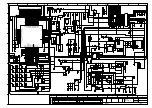
Figure 3-16. Synthesizer Block Diagram (900 MHz)
3.1.4.1 Reference Oscillator Y701
The radio's frequency stability and accuracy is derived from the Voltage-Controlled Temperature-
Compensated Crystal Oscillator (VCTCXO), Y701. This 16.8 MHz oscillator is controlled by the
voltage from the AUX_DAC pin of the Trident IC, U702, that can be programmed through a serial
peripheral interface (SPI). The oscillator output at pin 3 is coupled through capacitor C736 to the
Trident IC reference oscillator input. This reference is then passed through an internal buffer and is
then coupled to the external BJT buffer (comprised of U746 and supporting circuitry) via C739.
These buffers provide isolation for the 16.8 MHz output to the controller circuitry and ABACUS IC.
Components L753 and C754 form a low-pass filter to reduce the harmonics of the 16.8 MHz.
3.1.4.2 Trident IC U702
The Trident IC, U702, is a multiple protocol, multiple band transceiver Motorola-proprietary, CMOS
IC, with built-in dual-port modulation. The Trident IC incorporates frequency division and comparison
circuitry to keep the VCO signals stable. The Trident IC is controlled by the MCU through a serial
bus. All of the synthesizer circuitry is enclosed in rigid metal cans on the transceiver board to reduce
interference effects. Separate power supply inputs are used for the various functional blocks on the
IC. Inductors L727, L733, L735, L738 and L741 provide isolation between the IC and the different
power supplies. Host control is through a four-wire, smart SPI interface (pins D8, D9, D10 and C11).
Some of the Trident IC functions include frequency synthesis, reference clock generation,
modulation control, voltage multiplication and filtering, near-integer spurious reduction, RF divide-by-
two and auxiliary SPI.
3.1.4.3 Synthesizer
Frequency synthesis functions include a low band and high band mode prescaler, a phase detector,
a programmable loop divider and its control logic, a charge pump, and a lock detector output.
Fractional-N synthesizer principles of operation are covered in detail in the manufacturers' literature.
No similar discussion will be attempted here.
3.1.4.4 Clocks
U702, pin K5 (REF_IN), is the 16.8 MHz reference oscillator input from the VCTCXO (Y701).
TRIDENT IC
LOOP
FILTER
PRESCALAR
BUFFER
16.8MHz
16.8MHz
BUFFER
PRE
BUFFER
TX LO
RX LO
TX
BUFFER
900 TX
900 RX
16.8 MHz REFERENCE CLOCK (To Controller and Abacus IC)
TX VCO
RX VCO
Содержание APX 2000
Страница 1: ...APXTM TWO WAY RADIOS APX 1000 APX 2000 APX 4000 APX 4000Li DETAILED SERVICE MANUAL ...
Страница 4: ......
Страница 6: ...iv Document History Notes ...
Страница 8: ...Notes vi Commercial Warranty ...
Страница 10: ...Notes ...
Страница 22: ...xiv List of Figures Notes ...
Страница 165: ...Troubleshooting Waveforms Clocks 6 3 6 2 2 4 MHz Clock Trace 1 Trace recorded at R6113 Figure 6 2 4 MHz Clock Waveform ...
Страница 172: ...6 10 Troubleshooting Waveforms Audio SSI 6 3 4 BCLK Trace 1 Trace recorded at R6107 Figure 6 9 Audio SSI BCLK Waveform ...
Страница 174: ...6 12 Troubleshooting Waveforms RX SSI 6 4 2 DA Trace 1 Trace recorded at R2805 Figure 6 11 RX SSI DA Waveform ...
Страница 175: ...Troubleshooting Waveforms RX SSI 6 13 6 4 3 FSYNC Trace 1 Trace recorded at R2804 Figure 6 12 RX SSI FSync Waveform ...
Страница 177: ...Troubleshooting Waveforms TX SSI 6 15 6 5 2 DA Trace 1 Trace recorded at R2817 Figure 6 14 TX SSI DA Waveform ...
Страница 178: ...6 16 Troubleshooting Waveforms TX SSI 6 5 3 FSYNC Trace 1 Trace recorded at R2807 Figure 6 15 TX SSI FSync Waveform ...
Страница 179: ...Troubleshooting Waveforms SPI 6 17 6 6 SPI 6 6 1 CLK Trace 1 Trace recorded at R2803 Figure 6 16 SPI CLK Waveform ...
Страница 180: ...6 18 Troubleshooting Waveforms SPI 6 6 2 CS Trace 1 Trace recorded at R6602 Figure 6 17 CS Waveform ...
Страница 182: ...6 20 Troubleshooting Waveforms I2C BUS 6 7 2 SCL 5V Trace 1 Trace recorded at R2204 Figure 6 19 I2C Bus SCA 5V Waveform ...
Страница 183: ...Troubleshooting Waveforms I2C BUS 6 21 6 7 3 SDA Trace 1 Trace recorded at R6209 Figure 6 20 I2C Bus SDA Waveform ...
Страница 187: ...Troubleshooting Waveforms USB 6 25 6 10 USB 6 10 1 D Trace 1 Trace recorded at TP F_GCAI_USB Figure 6 24 USB D Waveform ...
Страница 188: ...6 26 Troubleshooting Waveforms USB 6 10 2 D Trace 1 Trace recorded at TP F_GCAI_USB Figure 6 25 USB D Waveform ...
Страница 190: ...6 28 Troubleshooting Waveforms SDRAM 6 11 2 CLKX Trace 1 Trace recorded at TP6308 Figure 6 27 SDRAM CLKX Waveform ...
Страница 226: ...6 64 Troubleshooting Waveforms LF CW on Spectrum Analyzer Notes ...
Страница 284: ...8 4 Schematics Boards Overlays and Parts Lists List of Transceiver Schematics and Board Overlays Notes ...
Страница 688: ...Index 4 Index Notes ...
Страница 689: ...Title Page ASTRO APX 1000 Digital Portable Radios Section 2 VHF UHF1 UHF2 700 800 MHz APX 1000 ...
Страница 690: ...ii Notes ...
Страница 695: ...List of Tables xi Related Publications APX 1000 Digital Portable Radios Basic Service Manual 68012004056 ...
Страница 700: ...xvi List of Figures Notes ...
Страница 756: ...4 6 Troubleshooting Procedures Power Up Self Check Diagnostics and Repair Not for Field Use Notes ...
Страница 806: ...5 50 Troubleshooting Charts PA Failure Notes ...
Страница 809: ...Troubleshooting Waveforms Clocks 6 3 6 2 2 4 MHz Clock Trace 1 Trace recorded at R6113 Figure 6 2 4 MHz Clock Waveform ...
Страница 816: ...6 10 Troubleshooting Waveforms Audio SSI 6 3 4 BCLK Trace 1 Trace recorded at R6107 Figure 6 9 Audio SSI BCLK Waveform ...
Страница 818: ...6 12 Troubleshooting Waveforms RX SSI 6 4 2 DA Trace 1 Trace recorded at R2805 Figure 6 11 RX SSI DA Waveform ...
Страница 819: ...Troubleshooting Waveforms RX SSI 6 13 6 4 3 FSYNC Trace 1 Trace recorded at R2804 Figure 6 12 RX SSI FSync Waveform ...
Страница 821: ...Troubleshooting Waveforms TX SSI 6 15 6 5 2 DA Trace 1 Trace recorded at R2817 Figure 6 14 TX SSI DA Waveform ...
Страница 822: ...6 16 Troubleshooting Waveforms TX SSI 6 5 3 FSYNC Trace 1 Trace recorded at R2807 Figure 6 15 TX SSI FSync Waveform ...
Страница 823: ...Troubleshooting Waveforms SPI 6 17 6 6 SPI 6 6 1 CLK Trace 1 Trace recorded at R2803 Figure 6 16 SPI CLK Waveform ...
Страница 824: ...6 18 Troubleshooting Waveforms SPI 6 6 2 CS Trace 1 Trace recorded at R6602 Figure 6 17 CS Waveform ...
Страница 826: ...6 20 Troubleshooting Waveforms I2C BUS 6 7 2 SCL 5V Trace 1 Trace recorded at R2204 Figure 6 19 I2C Bus SCA 5V Waveform ...
Страница 827: ...Troubleshooting Waveforms I2C BUS 6 21 6 7 3 SDA Trace 1 Trace recorded at R6209 Figure 6 20 I2C Bus SDA Waveform ...
Страница 831: ...Troubleshooting Waveforms USB 6 25 6 10 USB 6 10 1 D Trace 1 Trace recorded at TP F_GCAI_USB Figure 6 24 USB D Waveform ...
Страница 832: ...6 26 Troubleshooting Waveforms USB 6 10 2 D Trace 1 Trace recorded at TP F_GCAI_USB Figure 6 25 USB D Waveform ...
Страница 834: ...6 28 Troubleshooting Waveforms SDRAM 6 11 2 CLKX Trace 1 Trace recorded at TP6308 Figure 6 27 SDRAM CLKX Waveform ...
Страница 1008: ...8 178 Schematics Boards Overlays and Parts Lists Transceiver RF Boards UHF2 84012621001 Notes ...
Страница 1062: ...8 234 Schematics Boards Overlays and Parts Lists Keypad Board M2 and M3 PC000261A01 Notes ...
Страница 1063: ...Title Page ASTRO APX 1000 APX 2000 APX 4000 APX 4000 Li Digital Portable Radios Section 3 Appendices ...
Страница 1064: ...ii Notes ...
Страница 1068: ...Notes A 4 EMEA Warranty Service and Technical Support Further Assistance From Motorola ...
Страница 1072: ...B 4 LACR Replacement Parts Ordering and Motorola Service Centers Motorola Service Centers Notes ...
Страница 1090: ...Glossary 10 Glossary Notes ...
Страница 1094: ...Index 4 Index Notes ...
Страница 1095: ......


