


AP-7131N-FGR Access Point Product Reference Guide
2-14
To install the access point on a ceiling T-bar:
1.
Motorola recommends you loop a safety wire—with a diameter of at least 1.01 mm (.04 in.),
but no more than 0.158 mm (.0625 in.) —through the tie post (above the console connector)
and secure the loop.
2.
If desired, install and attach a security cable to the access point’s lock port.
3.
Attach the radio antennas to their correct connectors.
For more information on available antennas, see
Antenna Options on page 2-4
.
4.
Cable the access point using either the Power Injector or an approved power supply.
For Power Injector installations:
a. Connect a RJ-45 CAT5e (or CAT6) Ethernet cable between the network data supply (host)
and the Power Injector
Data In
connector.
b. Connect a RJ-45 CAT5e (or CAT6) Ethernet cable between the Power Injector
Data &
Power Out
connector and the access point’s GE1/POE port.
c. Ensure the cable length from the Ethernet source to the Power Injector and access point
does not exceed 100 meters (333 ft). The Power Injector has no On/Off power switch.
The Power Injector receives power as soon as AC power is applied. For more information
on using the Power Injector, see
Power Injector System on page 2-7
.
For standard 48-Volt Power Adapter (Part No. 50-14000-247R) and line cord installations:
a. Connect a RJ-45 CAT5e (or CAT6) Ethernet cable between the network data supply (host)
and the access point’s GE1/POE port.
b. Verify the power adapter is correctly rated according the country of operation.
c. Connect the power supply line cord to the power adapter.
d. Attach the power adapter cable into the power connector on the access point.
e. Plug the power adapter into an outlet.
5.
Verify the behavior of the LEDs. For more information, see
LED Indicators on page 2-18
.
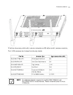
6.
Align the bottom of the ceiling T-bar with the back of the access point.
7.
Orient the access point’s chassis by its length and the length of the ceiling T-bar.
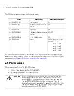
8.
Rotate the access point chassis 45 degrees clockwise.
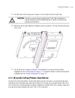
CAUTION
Do not supply power to the access point until the cabling of the unit is
complete.
!
Содержание AP-7131N-FGR
Страница 1: ...AP 7131N FGR Access Point Product Reference Guide ...
Страница 3: ...AP 7131N FGR Access Point Product Reference Guide 72E 126727 01 Revision A September 2009 ...
Страница 4: ......
Страница 55: ...Hardware Installation 2 11 ...
Страница 68: ...AP 7131N FGR Access Point Product Reference Guide 2 24 ...
Страница 90: ...AP 7131N FGR Access Point Product Reference Guide 3 22 ...
Страница 148: ...AP 7131N FGR Access Point Product Reference Guide 4 58 ...
Страница 300: ...AP 7131N FGR Access Point Product Reference Guide 6 72 ...
Страница 338: ...AP 7131N FGR Access Point Product Reference Guide 7 38 ...
Страница 635: ...Configuring Mesh Networking 9 23 5 Define a channel of operation for the 802 11a n radio ...
Страница 648: ...AP 7131N FGR Access Point Product Reference Guide 9 36 ...
Страница 672: ...AP 7131N FGR Access Point Product Reference Guide 10 24 line con 0 line vty 0 24 end ...
Страница 692: ...AP 7131N FGR Access Point Product Reference Guide B 14 ...
Страница 698: ...AP 7131N FGR Access Point Product Reference Guide B 20 ...
Страница 702: ...AP 7131N FGR Access Point Product Reference Guide C 4 ...
Страница 707: ......
Страница 708: ...MOTOROLA INC 1303 E ALGONQUIN ROAD SCHAUMBURG IL 60196 http www motorola com 72E 126727 01 Revision A September 2009 ...


