HC05A24EM USER’S MANUAL
MOTOROLA
2-2
2
2.1.1
Reset Select Header (P4)
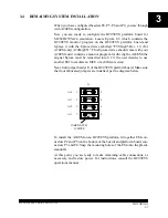
Jumper header P4 controls the path of a target reset. The diagram below
shows the factory configuration: the fabricated jumper between pins 1
and 2 enables your software to control resets. This is the only correct P4
configuration for an A24EM that is part of an MMDS05.
NOTE
The P4 pins 2 and 3 configuration is not correct for an
A24EM that is part of an MMDS05 system. Such a con-
figuration would interfere with correct operation of the
RESETIN and RESETOUT commands.
2.1.2
COP Disable Header (P5)
Jumper header P5 allows the user to enable/disable the internal COP
during software development. The diagram below shows the factory
configuration: the fabricated jumper between pins 1 and 2 enables the
internal COP. To disable it, remove the fabricated jumper between pins
1 and 2. The jumper setting is sampled once on power on or reset.
Changing the jumper setting after reset will have no effect on the inter-
nal COP.
1
2
3
P4
EVS
TARGET
FABRICATED
JUMPER
TARGET RESET
DRIVEN FROM
1
2
P5
OPEN = COP OFF
FABRICATED
JUMPER
COP DISABLE
CLOSE = COP ON
Содержание A24EM
Страница 17: ...HC05A24EM USER S MANUAL MOTOROLA 2 6 2 ...


