7A
7B
DIN912
M5x10
A
-
+
EN
EN
03. INSTALLATION
INSTALLING THE RACK
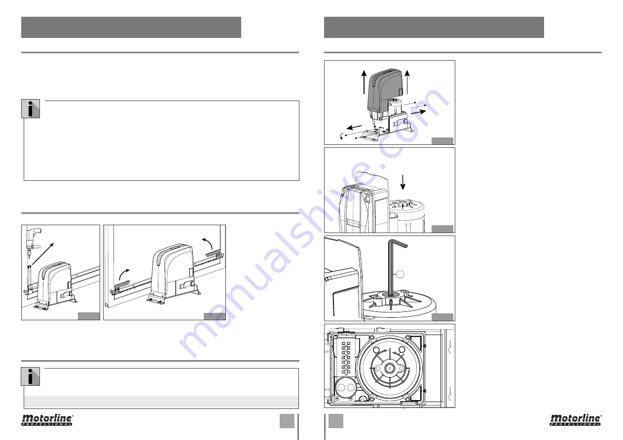
CLUTCH ADJUSTMENT
03. INSTALLATION
6 •
Pull another element of the rack above, using a piece of additional rack teeth to synchronize the two
elements (Fig. 22).
7 •
Use a level again to make sure that rack is perfectly level.
8 •
Manually move the gate and carry out the operations of attachment such as with the first element,
proceeding up to the end of the gate.
1 •
After having rack
nstalled, take the gate
back to the closed
position and position
the limit swicth plate on
the rack. In this closed
position, the plate should
trigger the limit switch of
the motor.
2 •
Tighten the screws
DIN912 M5x12 included in
the pack, until it touches
the rack, squeezing it.
1 •
Unbolt the screws and remove the cover.
2 •
Access the adjusting screw. Slide the central box
forward.
3 •
Adjust the screw in the upper part of the engine.
To do this, it will require a 6mm umbrako key as
shown in the image (A).
4 •
Do a test to the motor’s irreversibility. To do that,
just move the gate manually. If the gate is moving, it is
necessary to refine the screw by turning clockwise (+).
If the gate does not move at idle, it means that the
screw is tightened too much. Turn it counterclockwise
(-) until the engine moves the gate at idle.
The tuning must achieve a balance between the gate ‘s
irreversibility and the engine’s power.
INSTALLING LIMIT SWITCH PLATE
MAINTENANCE AND REPAIRS
•
This motor can work with all types of racks.
•
When installing nylon rack, make the application following the same steps described in the
previous paragraphs. Start by placing the gate in the closed position, support the first meter
of rack pinion on the engine and keeping it level horizontally, screw the first screw. Go opening
the gate and tightening the remaining bolts. Continue adding more rack parts and repeating
the same steps to complete the installation.
•
Make sure that, during the gate travel, all the rack elements mesh correctly with the pinion.
•
Do not, on any occasion, weld the rack elements either to the spacers. For fixing these, use
screws and washers like in the Fig.20.
•
Do not use grease or other lubricants between rack and pinion.
Carry out the following operations at least every 6 months:
•
Check the efficiency of the release system.
•
Check the efficiency of the safety devices and accessories.
• For any repairs, pls contact the authorised repair centers.
Fig. 25
Fig. 26
Fig. 27
Fig. 28
Fig. 23
Fig. 24
3 •
Move the gate to the open position and repeat the same process for the other limit switch plate.
4 •
The limit switch plates should be installed as in
Fig. 24
.
left
right


