background image

6A

6B

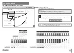
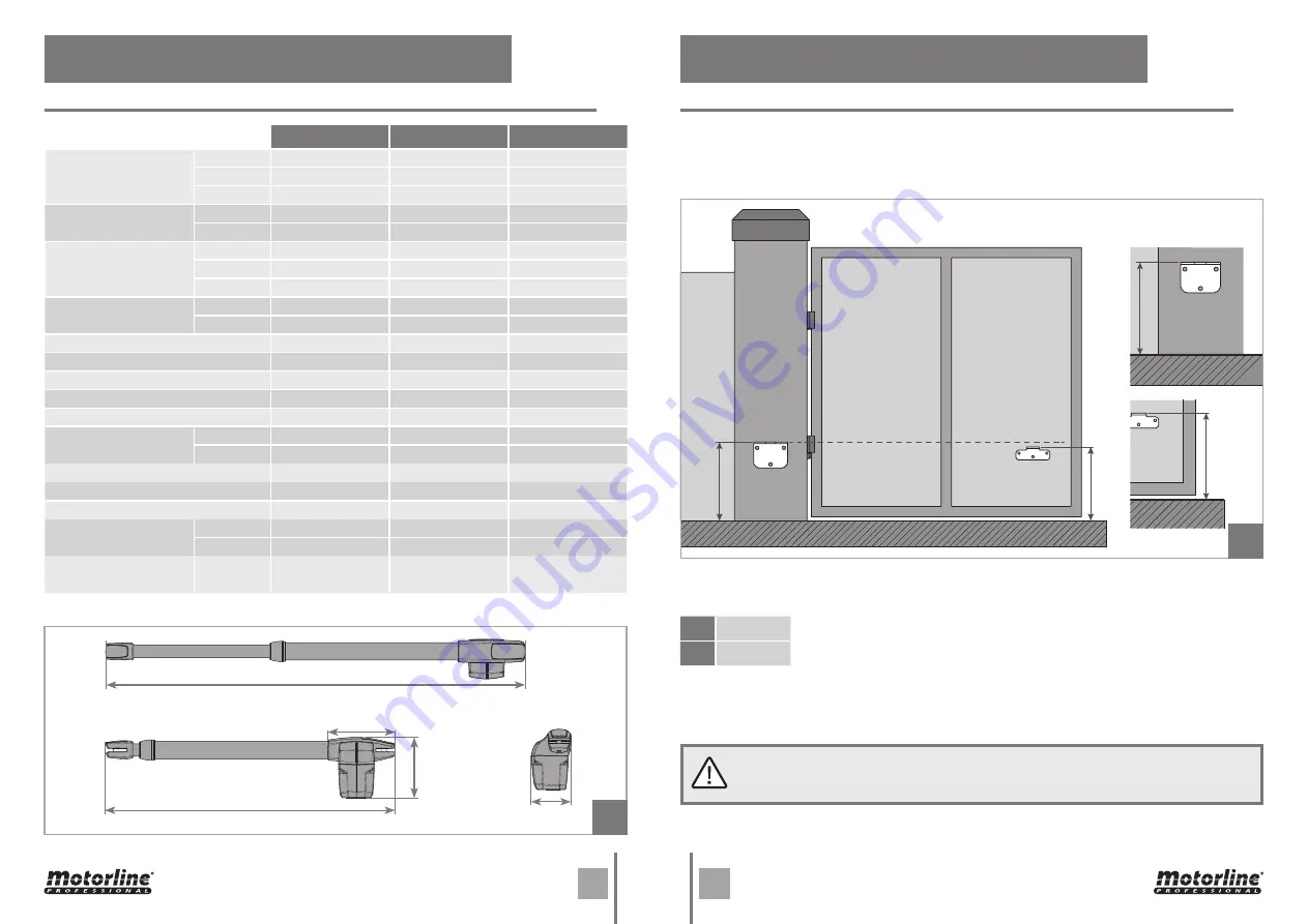
962mm || 1162mm || 1562mm

647mm || 747mm || 947mm

175mm

159mm

104mm

A

A

B

B

A

mm

B

A-

10mm

17

18

EN

EN

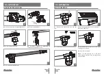
The operator 

LINCE 

must be installed with a small inclination , to prevent water infiltration 

through the extension arm.

For this, the front support must be fixed to the gate with a height lower than the height of 

the rear support. See example below:

Example: 

• If the height of the rear bracket (

dimension A

)is set at 600 mm, then the height of the front 

bracket (

dimension B

) will be 590 mm (600mm-10mm).

Dimension A 

• 

Vertical distance 

from the floor to the top of the rear support .

Dimension B 

• 

Vertical distance 

from the floor to the top of the front support.

• Set 

dimension A

 (this can be any size of your choice).

•  After you set 

dimension A

, subtract 

10mm

  to find 

dimensionB

.

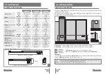
LINCE 300

 || 

400

 || 

600

 dimensions are the following:

It is very important that these dimensions are respected!

 Only this way can be assured 

the correct functioning and durability of the operators!

It is also very important to have a levelled ground/terrain!

LINCE300

LINCE400

LINCE600

• 

Power Supply

230V 

230Vac 50/60Hz

230Vac 50/60Hz

230Vac 50/60Hz

110V

110Vac 50/60Hz

110Vac 50/60Hz

110Vac 50/60Hz

24V

24Vdc

24Vdc

24Vdc

• 

Power

230/110V

230W

230W

230W

24V

60W

60W

60W

• 

Current

230V

1,3A

1,3A

1,3A

110V

2,5A

2,5A

2,5A

24V

1A to 3A

1A to 3A

1A to 3A

• 

RPM

230/110V

1400 RPM

1400 RPM

1400 RPM

24V

1600 RPM

1600 RPM

1600 RPM

• 

Noise level

LpA <= 50 dB (A)

LpA <= 50 dB (A)

LpA <= 50 dB (A)

• 

Force

2300N

2300N

2300N

• 

Operating temperatures

-25°C to 65°C

-25°C to 65°C

-25°C to 65°C

• 

Thermal protection

120°C

120°C

120°C

• 

Protection class

IP54

IP54

IP54

• 

Working frequence

230/110V

25%

25%

25%

24V

Intensive

Intensive

Intensive

• Opening time

8 sec. to 13 sec.

13 sec. to 18 sec.

20 sec. to 28 sec.

• 

Course

300mm

400mm

600mm

• 

Max leaf length

2500mm

3000mm

4000mm

• 

Capacitor

230V

8µF

8µF

8µF

110V

20µF

20µF

20µF

• 

Opening speed

230V

20mm/s

20mm/s

20mm/s

24V

23,5mm/s

23,5mm/s

23,5mm/ss

03. OPERATOR

04. INSTALLATION

TECHNICAL SPECIFICATIONS

HEIGHT OF THE SUPPORTS

Содержание LINCE Series

Страница 1: ...v11 0 REV 05 2022 EN USER S AND INSTALLER S MANUAL LINCE230V 110V 24V...

Страница 2: ...his product or the National Environment Agency for details on where and how they can take these items for environmentally safe recycling Business users should contact their vendor and check the terms...

Страница 3: ...ms of usage of the product in a safe manner and who understands the risks and dangers involved Children shouldn t play with the product or opening devices to avoid the motorized door or gate from bein...

Страница 4: ...se it until all safety conditions have been met In the event of tripping of circuits breakers of fuse failure locate the malfunction and solve it before resetting the circuit breaker or replacing the...

Страница 5: ...secure the Lower Part to Middle Part 02 Remove Lower Part The operator LINCE is a product developed exclusively for the automatic opening of swing gates Besides being pratical safe and powerful this...

Страница 6: ...cated in the figure to unlock 04 Operator unlocked Note To lock operator so it can work automatically must do it by turning the key anticlockwise Information engraved on the unlock shaft D Unlock B Lo...

Страница 7: ...assured the correct functioning and durability of the operators It is also very important to have a levelled ground terrain LINCE300 LINCE400 LINCE600 Power Supply 230V 230Vac 50 60Hz 230Vac 50 60Hz...

Страница 8: ...a 900 W 1095 a 1100 W 1495 a 1500 INTERIOR OPENING INSTALLATION QUOTAS 04 INSTALLATION On the Illustrated diagrams below and on the next page are the dimensions for the installation of the automated s...

Страница 9: ...99 95 92 360 92 93 95 96 97 99 95 91 380 92 93 94 96 97 95 91 400 92 93 94 95 95 91 W 695 a 700 W 900 a 905 EXTERNAL OPENING INSTALLATION QUOTAS 04 INSTALLATION On the Illustrated diagrams below and...

Страница 10: ...bricant for less friction Move the door manually to see if the door opens and closes uniformly and correctly without any irregular friction during its entire travel This will ensure that operator is n...

Страница 11: ...It is important to use mechanical stoppers in the opening and closing position of the gate If not respected components of the automation may suffer efforts for which they were not prepared and as a re...

Страница 12: ...l board Pull it out and send it to our MOTORLINE technical services for diagnosis 4 If the motors doesn t work remove them from installation site and send to our MOTORLINE technical services for diagn...

Страница 13: ...d to remove the automatism from the place it is installed because in this way it is possible to understand if the automatism can function properly connected directly to the current You should use a ne...

Страница 14: ...a homogeneous layer of lubricant over the arm Remove front and rear caps Place a small amount of lubricant on the holes that contains support pins Install caps on the respective holders Make sure that...

Отзывы: