


The Interface Solution Experts 43
SPA
2
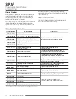
Programmable Current/Voltage
Limit Alarm Trips
CE Conformity
Installation of any Moore Industries’ products that
carry the CE certification
must
adhere to the guide-
lines as stated in order to meet the requirements set
forth in the European EMC and Low Voltage Directives
(EN 61326 and EN 61010). Consult the factory for the
most current information on products that have been
CE certified.
Operation
Once programmed, calibrated, installed, and supplied
with the correct power, the SPA
2
alarm begins to oper-
ate immediately. Depending upon environmental con-
ditions, it can be expected to operate unattended for
extended periods of time.
Maintenance
Moore Industries suggests a quick check for terminal
tightness and general unit condition every 6-8 months.
Always adhere to any site requirements for pro-
grammed maintenance.
Customer Support
Moore Industries is recognized as the industry leader
in delivering top quality to its customers in products
and services. We perform a battery of stringent qual-
ity assurance checks on every unit we ship. If any
Moore Industries product fails to perform up to rated
specifications, call us for help. Our highly skilled staff
of trained technicians and engineers pride themselves
on their ability to provide timely, accurate, and practi-
cal answers to your process instrumentation ques-
tions.
Factory phone numbers are listed on the back cover
of this manual.
If problems involve a particular SPA
2
, there are sev-
eral pieces of information that can be gathered
before you call the factory
that will help our staff get
the answers you need
in the shortest time possible
.
For fastest service, gather the complete model and
serial number(s) of the problem unit(s) and the job
number of the original sale.
Installation
Installation consists of physically mounting the unit
and completing the electrical connections.
Mounting
The SPA
2
is housed in a “universal” DIN case that
can be mounted on both 35mm G-type (EN50035) and
35mm Top-Hat (EN50022) DIN-rail.
To mount the SPA
2
on a Top-Hat DIN-rail, seat the
upper extrusion on the unit back panel over the top
lip of the rail and pivot downward until the housing
locks into place.
To mount the unit on a G-type rail, seat the
extrusion under the top lip of the rail and again,
pivot downward.
When mounting multiple units, like a rack or
cabinet, make sure to allow adequate vertical
spacing for pivoting the units.
Making the Electrical Connections
Refer to Figure 3 (SPA
2
Front Panel Configuration) or
Figure 19 (SPA
2
PC Configuration) for electrical con-
nections.
Recommended Ground Wiring
Practices
Moore Industries recommends the following ground
wiring practices:
• Any Moore Industries product in a metal case or
housing should be grounded.
• The protective earth conductor must be
connected to a system safety earth ground
before making any other connections.
• All input signals to, and output signals from,
Moore Industries’ products should be wired
using a shielded, twisted pair technique.
Shields are to be connected to an earth or
safety ground at the unit itself.
• The maximum length of unshielded input
and/or output signal wiring should be
two inches.


