30
Rev. 1.0
2016/7/30
SS03/05/10-EC Hardware Manual
+86-400-820-9661
3.2 Y1, Y2, Y3 and Y4 Digital Outputs
•
Y1 can be used as an alarm signal output. It can also be used as a static in position signal
output (static, checking in position when the motor is stopped), or as a dynamic in position signal
output (dynamic, checking in position all the time).
•
Y2 can be used as a tach signal output. Tach output produces pulses relative to the motor
position with configurable resolution. It can also be used as a static in position signal output
(static, checking in position when the motor is stopped), or as dynamic in position signal output
(dynamic, checking in position all the time), or as a timing signal output (50 pulses per rotation).
•
Y3 can be used as a signal output to release a brake. It can also be used as a static in position
signal output (static, checking in position when the motor is stopped), or as a dynamic in position
signal output (dynamic, checking in position all the time).
•
Y4 can be used as a static in position signal output (static, checking in position when the motor
is stopped), or as a dynamic in position signal output (dynamic, checking in position all the time).
Use
Step-Servo Quick Tuner
software for Y1, Y2, Y3 and Y4 function configuration.
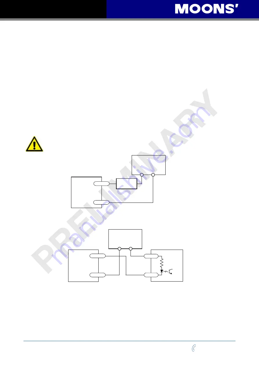
The following graphs show some common connection methods for the outputs:
NOTE: Do not connect the outputs to more than 30VDC power supply. And the
current of each output terminal must not exceed 100mA.
Connecting a sinking output
Connecting a sinking output to a PLC’s input
Connecting a sourcing output to a PLC’s input
Driving a relay
SS-EC
Drive
5-24 VDC
Power Supply
+
–
Load
Y1/2/3/4-
Y1/2/3/4-
Y1/2/3/4-
Y1/2/3/4-
Y1/2/3/4+
Y1/2/3/4+
Y1/2/3/4+
Y1/2/3/4+
C
D
V
4
2
-
5
+
–
IN
COM
SS-EC
Drive
PLC
5-24 VDC
Power Supply
+
–
COM
IN
SS-EC
Drive
SS-EC
Drive
1N4935 suppression diode
5-24 VDC
Power Supply
+
–
relay
Power Supply
PLC


