background image

4

31-1000600  Rev. 0

Safety Information

ANTES DE COMENZAR


Lea estas instrucciones en su totalidad y atentamente.


IMPORTANTE

 – 

Conserve estas instrucciones 

para uso del inspector local. Cumpla con todos los códigos y 
ordenanzas gubernamentales.

• 

Nota para el Instalador 

 –


Asegúrese de que el 

Comprador conserve estas instrucciones.

• Nota para el Consumidor  –


Guarde estas 

instrucciones con su Manual del Propietario para referencia 
futura.

Si la unidad que recibió está dañada, se deberá comunicar de 
inmediato con su vendedor o fabricante.

Nivel de habilidad  –

 La instalación de esta unidad 

requiere un nivel básico de habilidades mecánicas, de 
carpintería y plomería. La correcta instalación del producto 
es responsabilidad del instalador. Si se producen fallas en el 
producto debido a una instalación inadecuada, la Garantía de 
Monogram no cubrirá las mismas. Para obtener información 
sobre la garantía, consulte el Manual del Propietario.

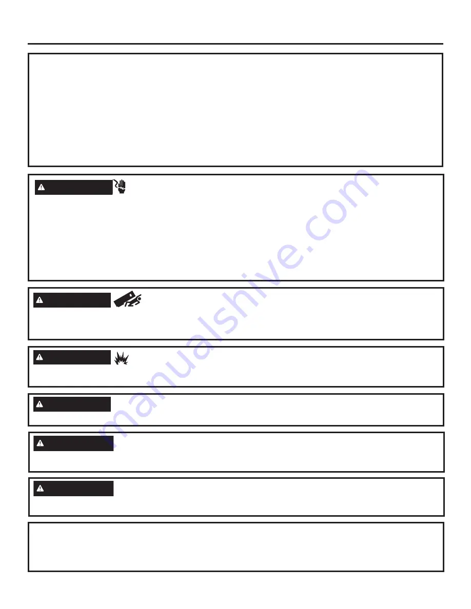
ADVERTENCIA


Riesgo de Caídas  

Estos electrodomésticos son inestables, especialmente cuando una puerta se encuentre abierta, y deben estar asegurados a fin 
de evitar caídas hacia adelante que podrían resultar en la muerte o en lesiones graves. Lea y siga las instrucciones de instalación 
en su totalidad para asegurar el electrodoméstico con el sistema anti volcaduras.

ADVERTENCIA


 Riesgo de Incendio o Explosión.

Mantenga cualquier material y vapores inflamables alejados del electrodoméstico. Si no se cumple con esto, se podrá producir 
una explosión, incendio o la muerte.

ADVERTENCIA


A fin de reducir el riesgo asociado con descargas, no permita que los niños menores de 3 años de edad 

tengan acceso a las partes pequeñas durante la instalación de este producto.

PRECAUCIÓN


Riesgo al levantar la puerta

Esta unidad es muy pesada. A fin de reducir el riesgo de lesión de una persona al maniobrar e instalar este electrodoméstico, se 
requiere contar con 3 personas para una correcta instalación.

PRECAUCIÓN


Mantenga los dedos fuera de los espacios de “riesgo de lastimaduras”; los espacios entre las puertas 

y entre las puertas y el gabinete son necesariamente pequeños. Tenga la precaución de cerrar las puertas cuando los niños se 
encuentren en el área. 

ADVERTENCIA


Riesgo de Descarga Eléctrica


Enchufe en un tomacorriente con conexión a tierra de 3 
cables.

No elimine el cable de conexión a tierra.

No use un adaptador.

Inmediatamente interrumpa el uso de un cable de suministro 
de corriente dañado. Si el cable de corriente se encuentra 
dañado, su reemplazo deberá ser realizado por un profesional 
calificado del servicio técnico, utilizando una pieza del servicio 
técnico autorizada por el fabricante.

No use un prolongador con este electrodoméstico. Si no se 
siguen estas instrucciones, se podrá producir la muerte, incen-
dios o descargas eléctricas.

Siga las instrucciones que figuran en la sección de Conexión 
de tierra de la unidad. 

Este electrodoméstico deberá ser instalado por algún medio en 
el cableado fijo del hogar o en un disyuntor para desconectar 
el electrodoméstico del suministro eléctrico luego de la instala-
ción.

FORMA ADECUADA DE DESCARTAR SU ELECTRODOMÉSTICO

Descarte o recicle su electrodoméstico de acuerdo con las Regulaciones Federales y Locales. Comuníquese con las autoridades 
locales para descartar o reciclar su electrodoméstico de forma ambientalmente segura.

Ŷ


Tenga en cuenta las opciones de reciclaje del material de embalaje de su electrodoméstico.

Содержание ZIF361NPRII

Страница 1: ...ers 24 30 and 36 Built In Column Refrigerators MONOGRAM COM Pour obtenir une version fran aise de ce manuel visitez notre site web sur monogram com Para consultar una version en espa ol de este manual...

Страница 2: ...low children under 3 years of age to have access to small parts during the installation of this product CAUTION Lifting Hazard This unit is very heavy To reduce the risk of person injury during maneuv...

Страница 3: ...a fa on de fixer l lectrom nager sur le dispositif antibasculement AVERTISSEMENT Risque d incendie ou d explosion Gardez les mati res et les vapeurs inflammables distance de l lectrom nager L omission...

Страница 4: ...s de edad tengan acceso a las partes peque as durante la instalaci n de este producto PRECAUCI N Riesgo al levantar la puerta Esta unidad es muy pesada A fin de reducir el riesgo de lesi n de una pers...

Страница 5: ...ounding the Unit 48 Flooring 48 Step 1 Remove Packaging 49 Step 2 Install Water Line 50 Step 3 Preparing Unit for Installation 51 Step 4 Install Anti tip Bracket 51 Step 5 Connecting Water Supply 52 S...

Страница 6: ...5 S E F B 5 1 8 13 0 Minimum to a Wall B 15 38 1 Minimum to a wall 16 9 16 42 1 cm on 30 models 19 48 3 cm on 36 models Dimensions 18 Models 24 Models 30 Models 36 Models A Overall Width Front 17 1 2...

Страница 7: ...uctions for Stainless Steel Door Panel Installation all installation types Installing Stainless Steel Door Panel Kits Instructions for Custom Overlay Door Panel Installation all installation types Ins...

Страница 8: ...8 31 1000600 Rev 0 Reversing the Door Swing This step can be done for all installation types...

Страница 9: ...to prevent tipping forward which could result in death or serious injury 1 4 Hex Screws Filter Removal Tool Filter Mounting Hook Compartment Door AVERTISSEMENT Suivez toutes les tapes pour inverser le...

Страница 10: ...Point Hazard Door hinges are under tension and should be left in the open position throughout the reversal process Closing the hinge can lead to a finger pinch point hazard Screws Screws AVERTISSEMENT...

Страница 11: ...models the red white black 5 pin wire connector will need to be removed from the control board and routed through the opposite corner bracket and reconnected to the control board to prevent pinching t...

Страница 12: ...Rotate filter to align arrow as shown Rectangular Slots Screws for Hinge Brackets Housing Key Holes STEP 4 MOVE LIGHT SWITCH HOUSING Cont Move the mounting bracket to the other side of the unit by re...

Страница 13: ...th two 1 4 hex head screws Verify the two 1 4 hex head screws are assembled to handle side of the products for both freezer and fresh food columns 1 4 Hex Screws Access Cover 1 4 Hex Screws Bottom hin...

Страница 14: ...tom screws 45 in lb 5 1 Nm Tighten top screws 45 in lb 5 1 Nm Carefully ensure door closes correctly and gasket aligns with case WARNING Follow all steps when reversing the door swing Failure to follo...

Страница 15: ...15 31 1000600 Rev 0 Instructions for Dual Integrated Installation New construction installation with 25 deep openings...

Страница 16: ...2 24 36 59 1 2 4 3 8 5 9 1 2 4 32 9 42 9 151 1 11 1 12 7 24 1 10 2 81 3 22 9 106 7 22 9 24 30 53 1 2 4 3 8 5 9 1 2 4 28 1 8 5 34 6 1 4 135 9 11 1 12 7 24 1 10 2 71 4 12 7 86 4 15 9 24 24 47 1 2 4 3 8...

Страница 17: ...is recommended on interior on all sides and top at front of opening TOOLS AND MATERIALS REQUIRED Metal shears 1 2 Phillips screwdriver Flathead screwdriver Putty knife Measuring tape Drill and 1 16 5...

Страница 18: ...is clean free of debris that could be collected on to or pinched in front of the wheels and damaging the floor Additionally it is recommended that the floor be protected with a plastic covering throug...

Страница 19: ...front of the unit SmartConnect Refrigerator Tubing Kits are available One 8 2 4m water line WX08X10006 is needed for each unit The waterline s will be taped to the floor using masking tape after anti...

Страница 20: ...cord is toward the top of the unit when installed Place the right hand unit in front of the installation opening in a way that the unit is in front of the intended installed location Install adhesive...

Страница 21: ...and follow the entire installation instructions for securing the appliance with the anti tip system 5 36 18 24 30 36 24 30 36 36 18 5 10 24 30 36 units 5 18 unit 10 24 30 36 units 12 18 unit STEP 4 IN...

Страница 22: ...tom screws and reassemble the screws at the top Tighten screws to tie units together BOTTOM FRONT UNIFICATION Install the bottom front unification bracket using a 3 8 driver 4 screws TOP UNIFICATION L...

Страница 23: ...r damage to your home Insert the molded end of the tubing into the refrigerator or freezer connection Tighten the compression nut until it is just hand tight Follow the instructions provided with the...

Страница 24: ...stallation String Power Cord String WARNING Electrical Shock Hazard To reduce the risk of electrical shock be careful during the remaining installation steps not to touch wiring or electrical componen...

Страница 25: ...wrench at the bottom of the leveling leg GMXVW KHLJKW RI XQLW WR PDWFK LQVWDOODWLRQ FXWRXW opening 84 The unit should be level and plumb with cabinetry NOTICE The rear leveling wheels and front level...

Страница 26: ...e units Locate OWHU DQG OWHU removal tool Filter should be as shown 5RWDWH OWHU WXUQ counterclockwise XVH OWHU UHPRYDO tool if needed 3XOO OWHU WRZDUG RX WR remove NOTE Water system will not function...

Страница 27: ...een the water filter access enclosures above displays STEP 11 INTERNAL UNIT PREPARATION Remove all tape cardboard and foam from each unit foam shipping supports may be located behind the left and righ...

Страница 28: ...partment temperature room temperature number of door openings and other use conditions If the freezer is operated before the water connection is made to the icemaker set the power switch to OFF Top wi...

Страница 29: ...refrigerator Slide the assembly toward the back wall until mounting screw hole is visible Secure AutoFill assembly with the T20 Torx screw removed earlier Ensure supply water is connected to the refr...

Страница 30: ...30 31 1000600 Rev 0 Instructions for Retro Fit Installation Existing construction installation with 24 deep openings that are 35 1 2 36 41 1 2 47 1 2 or 71 1 2 wide...

Страница 31: ...branch circuit or circuit breaker is recommended Install a properly grounded 3 prong electrical receptacle recessed into the back wall Electrical must be located on rear wall as shown Water line must...

Страница 32: ...operly Do not install the refrigerator freezer in a location exposed to water rain etc or direct sunlight Install it on a floor strong enough to support it fully loaded TOOLS AND MATERIALS REQUIRED Me...

Страница 33: ...l not close properly STEP 1 REMOVE PACKAGING Cont Remove front access cover from unit by removing two 1 4 Hex Screws some models have access cover in a box on the left side of the cabinet Place the co...

Страница 34: ...mper waterline and water fitting tee to the back wall The waterlines will be taped to the floor using masking tape after anti tip bracket installation Water Fitting Tee Water Line Jumper STEP 2 INSTAL...

Страница 35: ...nsformer into the case top provided in ZKUN kit and secure it with the existing 1 4 hex screws to left front of case top 3 Connect the 2 pin transformer connector to the heater connector and 3 pin con...

Страница 36: ...unit from rolling over the waterline during installation Do not tape near the cabinet front in order to keep tape hidden under the unit WARNING Tip Over Hazard These appliances are top heavy especiall...

Страница 37: ...et to the bottom screws and reassemble the screws at the top Tighten screws to tie units together BOTTOM FRONT UNIFICATION Install the bottom front unification bracket using a 3 8 driver 4 screws TOP...

Страница 38: ...ce rear access cover Make sure the power cord and ground wire are properly routed through the access cover cut out Repeat all steps for second unit CASE TRIM INSTALLATION Install the trim kit side rai...

Страница 39: ...old water supply is required for automatic icemaker operation The water pressure must be between 40 and 120 psi 275 827 kilopascals WARNING ELECTRIC SHOCK HAZARD Attach tubing clamp using existing hol...

Страница 40: ...both ends of the copper tubing Insert the tube into the union fitting on the unit and tighten the nut to the union Turn on the water to check for leaks SmartConnect Tubing NOTE The only GE Appliances...

Страница 41: ...RNING Tip Over Hazard These appliances are top heavy especially with any doors open and must be secured to prevent tipping forward which could result in death or serious injury WARNING Electrical Shoc...

Страница 42: ...PRYDO tool if needed 3XOO OWHU WRZDUG RX WR remove NOTE Water system will not function ZLWKRXW OWHU LQ SODFH STEP 9 FINAL EXTERNAL UNIT PREPARATION Cont Master Switch 1 4 Hex Screws 1 4 Hex Screws Fil...

Страница 43: ...ing into Cabinet Surround for details on installing the anti tip hardware Repeat for the second unit Verify the two 1 4 hex head screws are assembled to handle side of the products for both freezer an...

Страница 44: ...to be joined together If ice is not used frequently old ice cubes will become cloudy taste stale and shrink NOTE Icemaker works best between 40 and 120 PSI 275 827 kPa home water pressure STEP 12 STAR...

Страница 45: ...frigerator Slide the assembly toward the back wall until mounting screw hole is visible Secure AutoFill assembly with the T20 Torx screw removed earlier Ensure supply water is connected to the refrige...

Страница 46: ...46 31 1000600 Rev 0 Instructions for Single Integrated Installation New construction installation with 25 deep openings...

Страница 47: ...lation of an easily accessible shut off valve in the water line is required PLQLPXP RI FP ILQLVKHG UHWXUQ PDWFKLQJ cabinet exterior is recommended on interior on all sides and top at front of opening...

Страница 48: ...frigerator freezer where the tem perature will go below 55 F 13 C It will not run often enough to maintain proper temperatures Do not install the refrigerator freezer where temperatures will go above...

Страница 49: ...RE the unit is removed from the shipping skid Pin is located in the hardware kit Open the door approximately 45 but no wider than 90 to expose the hole in the back hinge bracket and install the limiti...

Страница 50: ...r line WX08X10006 is needed for each unit The waterline will be taped to the floor using masking tape after anti tip bracket installation Tubing should be long enough to extend to the front of the uni...

Страница 51: ...e hidden under the unit STEP 4 INSTALL ANTI TIP BRACKET Remove the anti tip bracket from the hardware kit Anti tip bracket should be mounted against the back wall or up to 25 1 2 64 7 cm maximum from...

Страница 52: ...ut until it is just hand tight Follow the instructions provided with the tubing Overtightening can cause leaks Turn on the water to check for leaks Freezer Water Supply House Water Supply Refrigerator...

Страница 53: ...t in death or serious injury WARNING Electrical Shock Hazard To reduce the risk of electrical shock be careful during the remaining installation steps not to touch wiring or electrical components insi...

Страница 54: ...wheels STEP 8 FINAL EXTERNAL UNIT PREPARATION FOR FLUSH INSTALLATION Make sure front surface of the door is 7 8 behind front face of surrounding cabinets BEFORE securing brackets to the surrounding ca...

Страница 55: ...for the second unit RFDWH EOXH DUURZ RQ OWHU 5RWDWH OWHU WR DOLJQ DUURZ as shown QVHUW OWHU LQWR SRVLWLRQ DQG URWDWH WXUQ FORFNZLVH XVH OWHU UHPRYDO tool if needed 5HWXUQ OWHU UHPRYDO WRRO WR mountin...

Страница 56: ...s not used frequently old ice cubes will become cloudy taste stale and shrink NOTE Icemaker works best between 40 and 120 PSI 275 827 kPa home water pressure Feeler Arm Feeler Arm Icemaker Icemaker Po...

Страница 57: ...the refrigerator Slide the assembly toward the back wall until mounting screw hole is visible Secure AutoFill assembly with the T20 Torx screw removed earlier Ensure supply water is connected to the r...

Страница 58: ...58 31 1000600 Rev 0 Stainless Steel Door Panel Installation This step can be done for all installation types...

Страница 59: ...se 3 adjustment set screws Use a 1 8 allen wrench to install the set screws in the order as instructed The set screws behind the top and bottom support brackets are partially hidden Bottom hinge cover...

Страница 60: ...t screws per panel If the panels do not lay flat they can be adjusted Start by adjusting the top corners and then moving to the bottom corners Each corner can be adjusted independently If the panel is...

Страница 61: ...MPLETE THE FOLLOWING STEPS Top cover assembly shipped in box on side of product Remove screws and nuts to remove rectangular cover Retain parts to build new top assembly Mount rectangular cover to bot...

Страница 62: ...o the outer trim Once the test fit is complete remove the trim and peel 8 10 of backer off of the top of the inner trim tape Without touching the exposed tape to the side of the door align the top of...

Страница 63: ...63 31 1000600 Rev 0 Custom Overlay Door Panel Installation This step can be done for all installation types...

Страница 64: ...nter should be 1 1 2 3 81 cm as shown 1 4 0 64cm 1 2 1 27cm 3 4 1 91cm Door Panel B A WARNING d Door Trim Pinch Point Hazard Improper installation can lead to a finger pinch point hazard between the s...

Страница 65: ...e panel Drill pilot holes with a 5 64 drill bit making sure to drill no deeper than 1 2 deep Install top and bottom mounting brackets provided with No 6 Phillips Head Screws Use 12 screws for 18 24 an...

Страница 66: ...djustment screws equally on the top of the panel bracket 2 adjustment screws per panel If the panels do not lay flat they can be adjusted Start by adjusting the top corners and then moving to the bott...

Страница 67: ...ter the top and bottom door panel brackets are secured by installing tightening all 12 set screws use 1 4 hex screw and square washer to secure the center mounting bracket Square Washer Center Mountin...

Страница 68: ...e door Without removing the backing to the tape strips test the fit of the trim to the side of the door 1 Align the top of the outer trim to the top of the door panel 2 Inner trim should fit between t...

Страница 69: ...shing to adhere the tape while keeping the trim in place until you have completely removed the tape backing Secure the top and bottom portions of the outer trim after the inner trim has been secured 1...

Страница 70: ...70 31 1000600 Rev 0 Notes...

Страница 71: ...71 31 1000600 Rev 0 Notes...

Страница 72: ...his book safety glasses or goggles should be worn NOTE Product improvement is a continuing endeavor at Monogram Therefore materials appearance and specifications are subject to change without notice 3...

Отзывы: