16
Technical service manual
REPLACING AND ADJUSTING THE PICK
UPS
- Open the weight-holder lid, first undoing the fixing screws.
- Remove the plastic guard of the central unit.
- Disconnect the pick up cable from the motherboard.
- Undo the two M8 dowels and remove the pick ups.
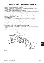
- Fit the new pair of pick ups, taking care that the two balls locate correctly inside the
recesses provided, then tighten the fixing dowels so that the pick ups move with just
a little friction.
Fit the pick ups marked I on the right and those marked E on the left (working from a
position facing the front of the machine).
- Reconnect the pick up cable.
Checks to ensure that the pick ups are operating correctly:
- Select the service program “96” to display the pick up data;
- fit an average-size 4WD wheel (e.g. 6 x 15” ) on the balancing machine and balance it
as accurately as possible.
- Imbalance the wheel by applying 100 grams (3.5 oz) to its outside.
- Perform a wheel spin to check the pick up signal values and synchronisation;
The values to be checked are the following:
- pick up synchronisation difference
F
from -2.0 to +2.0
- internal pick up signal
I
from 200 to 280
- external pick up signals
E
from 110 to 170
If the values displayed at the end of the wheel spin are not within the specified ranges,
adjust the dowels to regulate the tightness of the pick ups until the conditions are met.
These values are normally obtained with a tightening torque of about 2 Nm.
- Tighten the lock-nuts into a block then undo them slightly (about one side of the
hexagon) so that the Belleville washers present are operational.
During this operation the respective dowels should be kept still so that the pick up
preload conditions remain unchanged.
- Close the weight-holder lid and the plastic guard of the central unit again;
- Perform sensitivity calibration both in CAR environment with a car wheel and in
TRUCK environment with a truck wheel.
REPLACING THE CENTRAL UNIT
After making sure that the unit is really the cause of the machine’s malfunctions, re-
place it as described below:
- Open the weight-holder lid, first undoing the fixing screws.
- Remove the plastic guard of the central unit.
- Disconnect the sensor rod return spring from the body of the machine, unscrew the
fixing screws and remove the sensor from its seat. To access the return spring, remove
the protective cap close to the adjuster foot on the back of the machine.
- Disconnect the brake cylinder air line.
- Remove the motor and its support by unscrewing the three screws fixed to the beam
Содержание MT 2450
Страница 1: ...MT 2450 Code 4 131046_uk 12 2013 Technical service manual...
Страница 25: ...Technical service manual 25 UK Note...
Страница 27: ...Technical service manual 27 UK...
Страница 28: ...28 Technical service manual...
Страница 29: ...Technical service manual 29 UK Cod 4 101700...
Страница 30: ...30 Technical service manual...
Страница 31: ...Technical service manual 31 UK...
Страница 32: ...32 Technical service manual...
Страница 33: ...Technical service manual 33 UK Cod 457674B...
Страница 34: ...34 Technical service manual...
Страница 35: ...Technical service manual 35 UK Cod 4 104447A...

