7
6
ESCAPE
button or
LED ON/OFF
Active
SETTING
MENU or
SELECT
button
Use Rotary Knob or Arrow Buttons to adjust
ESCAPE
button or
LED ON/OFF
Active
SETTING
MENU or
SELECT
button
Use Rotary Knob or Arrow Buttons to adjust
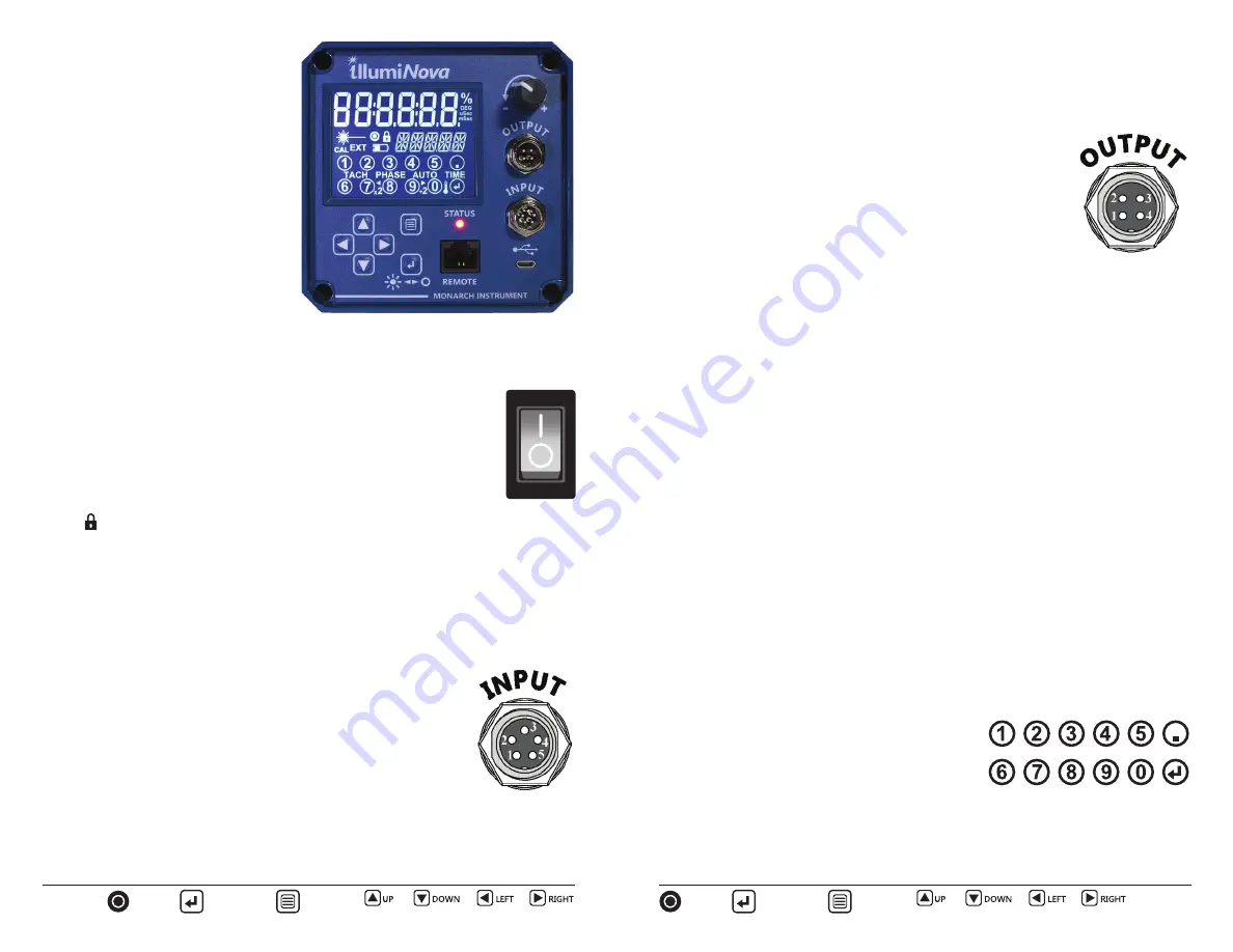
The LCD display shown to the right
has all segments on for demonstration
purposes. The display is capable of
showing 6 numeric and 5 alphanumeric
characters. The bottom section of the
display is a capacitive touchscreen. The
segment functions will be described in
the applicable sections.
STATUS LED
– Red in Standby mode
(LEDs not
fl
ashing) and Green in the run
mode (LEDs
fl
ashing). A Red LED may
also indicate an internal fault condition.
3.0 GETTING STARTED
3.1 Installation
Refer to illumiNova™ Installation Manual
for more information. Part number: 1071-4255-2XX (where XX=Revision)
3.2 Powering the Unit
To turn the unit on press the POWER SWITCH on the side to the right of
the control panel. When the “I” is depressed the power is on, when the
“O” is depressed the power is o
ff
.
When turned on the unit may be in Standby mode, meaning the display
will illuminate but the LEDs will not
fl
ash. The STATUS LED will be red.
The unit may be adjusted at this point if needed.
To turn the LEDs ON (or OFF) press the LED ON/OFF button. The locked
icon will show on the display and the STATUS LED will be green. The unit
will now run continuously.
To turn the unit o
ff
press the “O” on the POWER SWITCH.
Note:
The Standby mode may be disabled (in the MISC menu) in which case the
strobe may or may not be
fl
ashing depending on the last status when powered o
ff
.
3.3 Input / Output Connections
3.3.1 Input
The INPUT connector (Aviation Plug M12 x 5) has 5 pins for
connection of external trigger sources. These input signals
can drive the strobe in the External Mode. The sensor input
is compatible with Monarch’s inductive, proximity and optical
sensors.
Connections are as follows:
Isolated Input:
1 Isolated Input + 5 to 12 VDC @ 50mA max. (brown)
2 Isolated Input -
300Vdc Isolation. 10kHz max. (white)
Sensor Input:
3 +5V out
+5Vdc out 60mA (blue)
4 Signal Input
3 to 5 V DC pulse (black)
5 Common (GND) Common (gray)
3.3.2 Output
The OUTPUT connector (Aviation Plug M12 x 4) has 4 pins
3 of which are used for output signals. The strobe has two
outputs. The
fi
rst mimics the input pulse and can be used for
daisy-chaining multiple strobes. The second is a controlled
output from the strobe processor and is synchronous with the
actual
fl
ash of the strobe. Any delays or scaling of the input are
re
fl
ected in this second output pulse.
Note:
Output pulses are not isolated.
1 Pulse Out
5V (typ) Output @ 30mA. Controlled by Strobe (brown)
2 Repeater Out
5V (typ) Output @ 30mA. Mimics Input pulse (white)
3 Common (GND) Common (blue)
4.0 MODES OF OPERATION
4.1 Internal
Mode
The Internal Mode is the default mode of operation. It can also be selected in the
MODE menu option.
In the Internal mode the strobe generates the
fl
ash rate set by the user. The user can
set the
fl
ash rate in a number of ways:
4.1.1 Rotary
Knob
The user can dial the rotary knob in either direction to set the desired
fl
ash rate.
4.1.2 Arrow
Buttons
This method uses the four arrow buttons on the control panel. Pressing any button
will cause a digit on the
fl
ash rate display to start blinking – this is the digit that will
be edited. Pressing the UP
or DOWN
button will increment or decrement the
digit. The
fl
ash rate changes in real time if the Strobe is
fl
ashing. Using the LEFT
or RIGHT
button will change the digit that blinks and allow the user to edit
another digit. There is a rollover e
ff
ect when the digit is changed – if incrementing
the units digit 99 will roll over to 100. Pressing and holding the UP
or DOWN
button will cause the current digit to auto increment or decrement. If the user does
not increment or decrement a digit within 5 seconds the edit mode will be canceled.
4.1.3 Using the Numeric Touchscreen Keypad
To use the touchscreen keypad to enter a speci
fi
c
fl
ash rate press the MENU button once and the
display will show the numeric keypad with num-
bers 1 – 9, 0, Decimal Point and ENTER.
The Flash rate will default to the last setting and show the digits you are entering.
Simply enter your desired
fl
ash rate by pressing the digits followed by the Enter key.
Note that this is a capacitive touch sensitive keypad and will not respond if the user
is wearing gloves.
POWER
SWITCH


