11 Befehlsübersicht für die Computer-
Schnittstelle
Die jeweilige Schnittstelle und die Übertragungsrate
für die Fernsteuerung des Recorders über einen
Computer oder ein Terminal können im Menü RE-
MOTE ausgewählt werden (siehe Kap. 9.9).
Jedem Datenbyte (bestehend aus 8 Datenbits) geht
1 Startbit voraus und 1 Stoppbit folgt. Es wird kein
Paritätsbit übertragen.
Jeder Befehl besteht aus den folgenden 5 Daten-
bytes:
12 Festplatte auswechseln
Das Gerät ist mit einer 80-GB-Festplatte ausgestat-
tet. Diese kann gegen eine andere ausgewechselt
werden. Es lassen sich Festplatten mit Speicher-
kapazitäten von über 250 GB einsetzen. Eine Liste
von kompatiblen Festplatten finden Sie in Kap. 13.1.
12.1 Festplatte herausnehmen
1) Den Gehäusedeckel abschrauben (8 Schrauben)
und abnehmen.
2) Die Halterung über der Festplatte abschrauben
(2 Schrauben) und abnehmen.
3) Die Festplatte erst aus der IDE-Anschlussbuchse
ziehen, dann die 4-polige Steckverbindung für die
Stromversorgung von der Festplatte abziehen.
4) Die Festplatte herausnehmen.
12.2 Neue Festplatte einsetzen
1) Die 4-polige Steckverbindung an den Stromver-
sorgungsanschluss der Festplatte anschließen.
2) Die Pin-Leiste der Festplatte in die IDE-An-
schlussbuchse schieben.
3) Die Festplattenhalterung über die Festplatte set-
zen und festschrauben.
4) Den Gehäusedeckel wieder aufsetzen und fest-
schrauben.
●
Für den Austausch der Festplatte muss das Ge-
rät geöffnet werden. Darum sollte er nur von qua-
lifiziertem Fachpersonal durchgeführt werden.
●
Es ist nicht möglich, die aufgezeichneten Video-
daten per Computer aufzurufen. Bei Betrieb der
Festplatte auf einem Computer wird ihre FAT (file
allocation table) beschädigt.
11 List of Commands for the Computer
Interface
The corresponding interface and the baud rate for
the remote control of the recorder via a computer or
a terminal can be selected in the menu REMOTE
(see chapter 9.9).
Each data byte (consisting of 8 data bits) is prece-
ded by 1 start bit and succeeded by 1 stop bit. No
parity bit is transmitted.
Each command consists of the following 5 data
bytes:
19
GB
D
A
CH
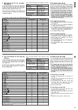
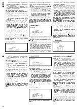
Funktion
Hexadezimalcode
ASCII-Zeichen
Taste MENU
4D
M
Taste SEARCH
73
s
Taste ENTER
0D
ENTER
Taste
/-
51
Q
Taste
5A
Z
Taste
/+
70
p
Taste SLOW
53
S
Taste REC
72
r
Taste PLAY
50
P
Taste REW (
)
4C
L
Taste PAUSE (
)
55
U
Taste STOP (
)
4E
N
Taste FF (
)
52
R
Bediensperre
4B
K
Taste für Kanal 1
31
1
Taste für Kanal 2
32
2
Taste für Kanal 3
33
3
Taste für Kanal 4
34
4
Bildschirmeinblendung, die informiert, ob zurzeit eine
timergesteuerte Aufnahme läuft
54
T
Die Funktionen der Bedientasten sind folgendermaßen kodiert:
Datenbyte
Codierung
1. Startbyte
FF (hexadezimal)
2. Voradresse (fest)
C0 (hexadezimal)
3. Recorder-Adresse
siehe Zeile ID im
Menü REMOTE
4. Funktionsbefehl
siehe Tabelle unten
5. Stoppbyte
7F (hexadezimal)
Data byte
Coding
1. Start byte
FF (hexadecimal)
2. Preaddress (fixed)
C0 (hexadecimal)
3. Recorder address
see line ID in the
menu REMOTE
4. Functional command
see table below
5. Stop byte
7F (hexadecimal)
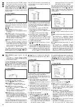
Function
Hexadecimal code
ASCII characters
Key MENU
4D
M
Key SEARCH
73
s
Key ENTER
0D
ENTER
Key
/-
51
Q
Key
5A
Z
Key
/+
70
p
Key SLOW
53
S
Key REC
72
r
Key PLAY
50
P
Key REW (
)
4C
L
Key PAUSE (
)
55
U
Key STOP (
)
4E
N
Key FF (
)
52
R
Lock
4B
K
Key for channel 1
31
1
Key for channel 2
32
2
Key for channel 3
33
3
Key for channel 4
34
4
Insertion on the screen to indicate if a timer-controlled
recording is being made
54
T
The functions of the control keys are coded as follows:
12 Replacing the Hard Disk
The unit is equipped with an 80 GB hard disk which
can be replaced by another one. Hard disks with a
storage capacity of more than 250 GB can be used.
A list of compatible hard disks can be found in chap-
ter 13.1.
12.1 Removing the hard disk
1) Unscrew the housing cover (8 screws) and
remove it.
2) Unscrew the bracket placed over the hard disk
(2 screws) and remove it.
3) First disconnect the hard disk from the IDE
connection jack, then disconnect the 4-pole
power supply connector from the hard disk.
4) Remove the hard disk.
12.2 Inserting a new hard disk
1) Connect the 4-pole connector to the power sup-
ply connection of the hard disk.
2) Slide the pin terminal of the hard disk into the IDE
connection jack.
3) Place the bracket over the hard disk and screw it
on.
4) Replace the housing cover and screw it on.
●
For replacing the hard disk, the unit must be
opened. Therefore, the replacement should be
carried out by skilled personnel only.
●
It is not possible to call the recorded video data
by computer. When operating the hard disk on a
computer, its FAT (file allocation table) will be
damaged.

