Mojix
®
STAR 1000 System User Manual
29
Appendix A: Location Configuration Guidelines
This section describes the setup and installation notes to estimate location. For most algorithm variations, the location
and orientation of the receiver and eNodes is essential for determining tag location. What follows is the description of
the coordinate system and the system components in it as well as how to enter this information so that it is accessible
by the software applications.
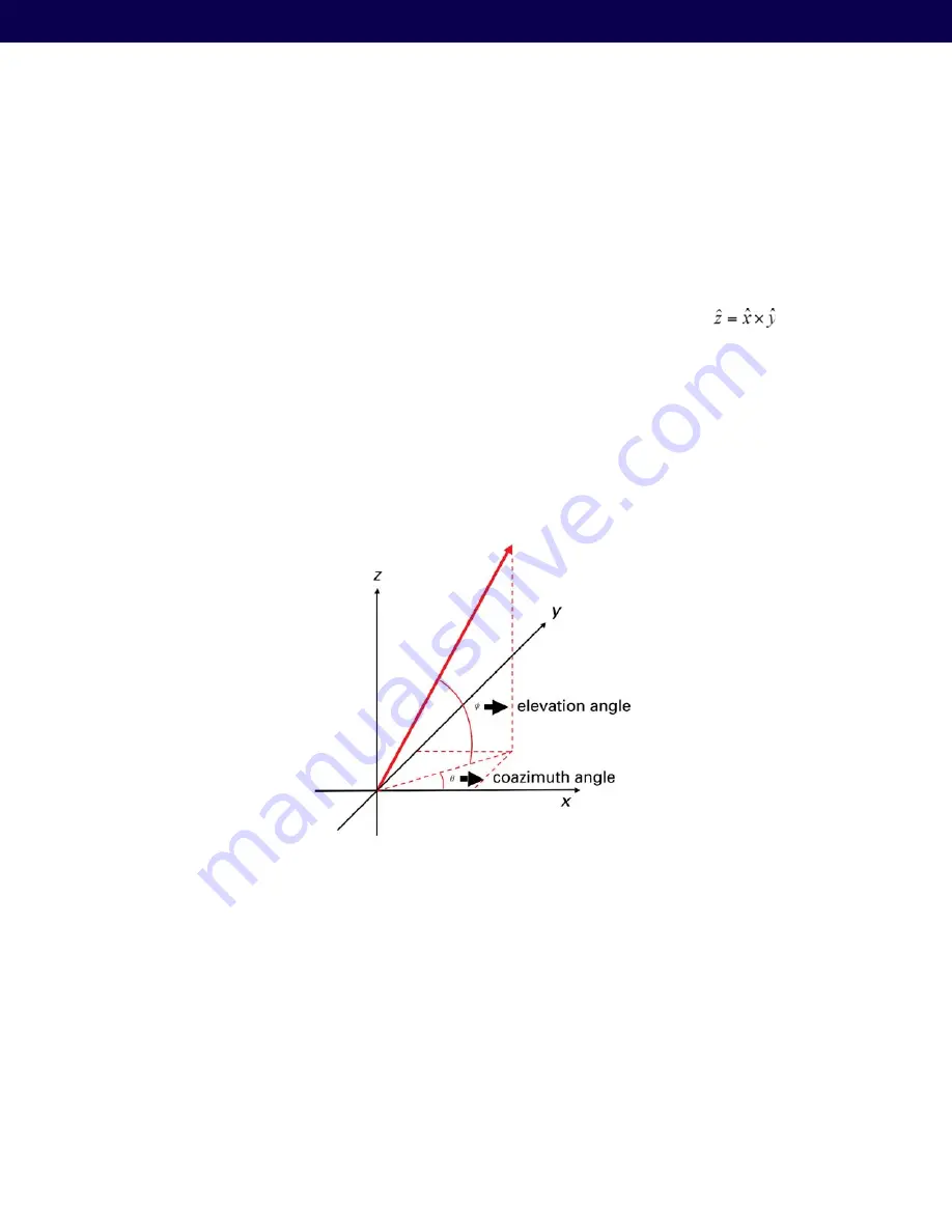
The location and orientation of both reader and eNodes will be made with respect to a coordinate system that must
be defined. The relationship between vectors x, y and z must follow the right hand rule, that is :
where x
denotes the vector product. The figure below shows an example of the relation between x, y and z.
The two angles that describe the beam boresight of both reader and eNodes must also be entered. These angles can
be seen in Fig. 1 and are defined as follows:
coazDeg: coazimuth angle, in degrees. It is an angle that starts at zero in the +x-direction, and increases moving toward
+y-direction.
elevDev: elevation angle, in degrees. Zero at the horizon, increases to +90 when pointing up.
Figure 30: Coordinate system
The last entry that must be configured is the reader roll angle. It indicates the rotation of the reader on its own axis (the
axis that corresponds to the beam boresight). The rotation values are as follows:
with power cord down, boresightRollDeg = 180
with power cord up, boresightRollDeg = 0
As a check on reader orientation, the 3rd element is at the end with the Ethernet connection. Look at dbPlot location
plot for the 4 antenna elements to make sure the boresightRollDeg field was entered correctly. The following table
illustrates a partial description of the fields.


