


22
Chapter 3. Feedback control loops
3.4
Modulation and scanning
Laser scanning is controlled by either an internal sweep genera-
tor or an external sweep signal. The internal sweep is a sawtooth
with variable period as set by an internal four-position range switch
(App. C), and a single-turn trimpot
RATE
on the front-panel.
The fast and slow servo loops can be individually engaged via
TTL
signals to the rear-panel associated front-panel switches. Setting
either loop to
LOCK
stops the sweep and activates stabilisation.
Fast control
MODULATION & SWEEP
MOD IN
+
0v
0v
Bias [3]
FAST OUT
TRIG
HF
FAST
BS
BIAS
RA
RAMP
BIAS
0v
LF sweep
0v
SPAN
0v
0v
Fixed offset [5]
+
OFFSET
SWEEP IN
+
RATE
Ramp
Slope [6]
INT/EXT
LOCK IN (FAST)
LOCK IN (SLOW)
0v
–
Mod [4]
0v
FAST = LOCK
SLOW = LOCK
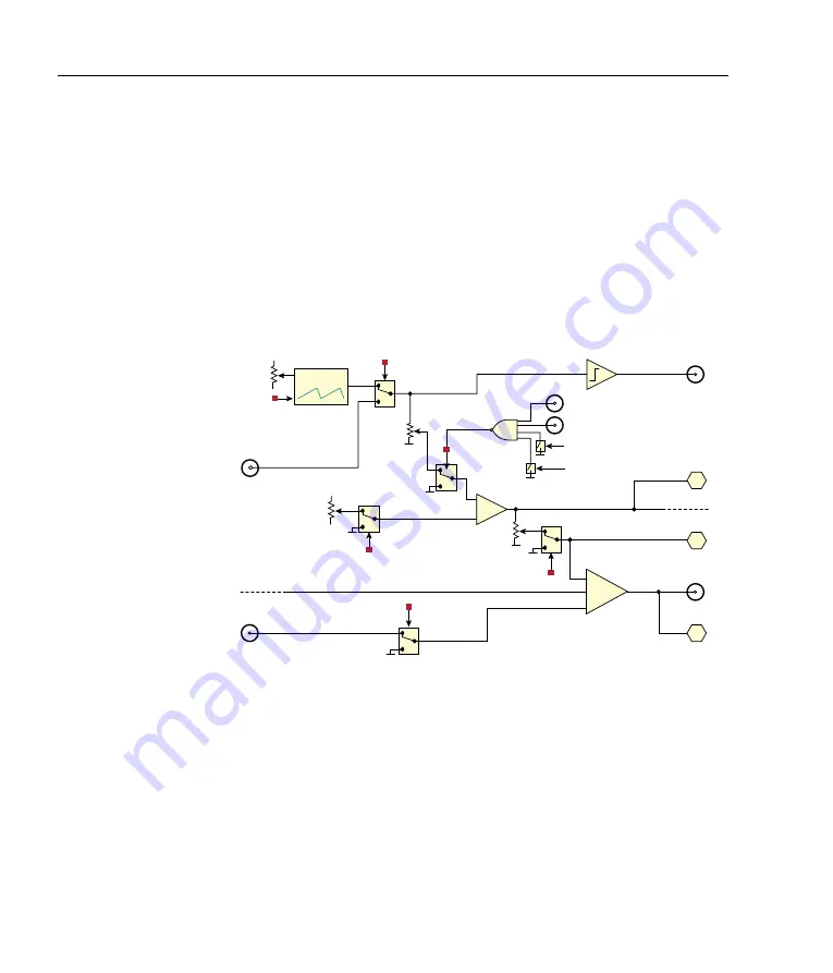
Figure 3.7:
Sweep, external modulation, and feedforward current bias.
The ramp can also be added to the fast output by enabling
DIP3
and adjusting the
BIAS
trimpot, but many laser controllers (such as
the
MOGL
abs
DLC
) will generate the necessary bias current based
on the slow servo signal, in which case it is unnecessary to also
generate it within the
FSC
.
Содержание FSC
Страница 1: ...Fast servo controller Version 1 0 4 Rev 2 4 hardware ...
Страница 36: ...32 Chapter 4 Application example Pound Drever Hall locking ...
Страница 44: ...40 Appendix C PCB layout ...
Страница 48: ...44 Appendix D 115 230 V conversion ...
Страница 51: ......


