4-522.4
3.
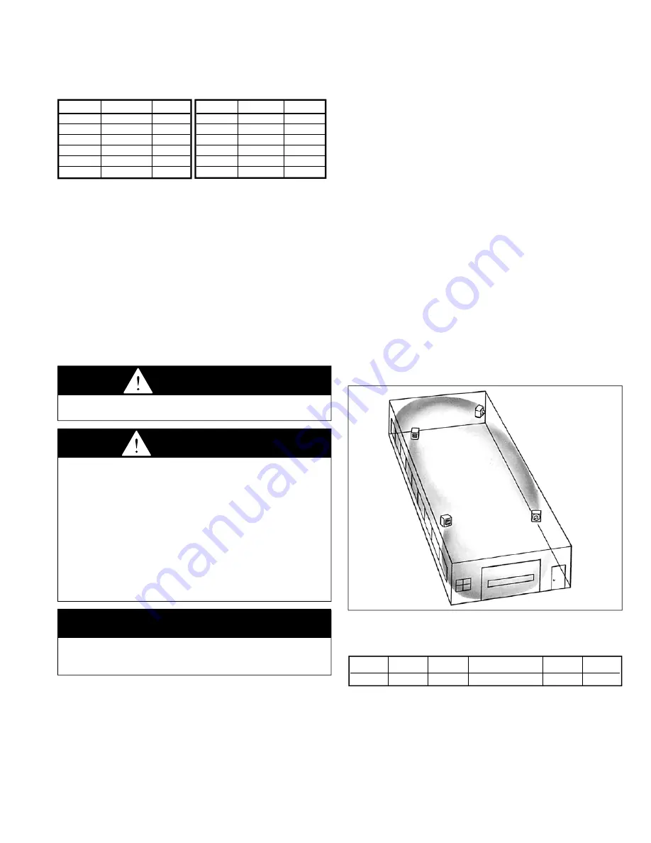
In multiple unit installations, arrange units so that each
supports the air stream of the next unit, thus creating
circulatory air movement in the area. See Figure 3.1. A large
portion of the heated air should be directed toward the side
of the building exposed to prevailing winds.
4.
When locating units, it is important to consider that the
exhaust vent piping must be connected to the outside
atmosphere.
5.
Be sure the structural support at the unit location site is
adequate to support the weight of the unit. For proper
operation the unit must be installed in a level horizontal
position.
6.
Do not install units in locations where the flue products
can be drawn into the adjacent building openings such as
windows, fresh air intakes, etc.
7.
Be sure that the minimum clearances to combustible
materials and recommended service clearances are
maintained. Units are designed for installation on with the
minimum clearances shown in Table 3.2.
8.
Do not install units in locations where gas ignition system is
exposed to water spray, rain, or dripping water.
9.
Mounting Height (measured from bottom of unit) at which
unit heaters are installed is critical. Refer to mounting height
information and heat throw data on page 17 of this manual.
The maximum mounting height for any unit is that height
above which the unit will not deliver heated air to the floor.
figure 3.1
typical unit locations
table 3.2
combustible material and service clearances
all model sizes
3
general information
Install and wiring of these oil-fired unit heaters must conform to
all applicable local codes, the National Electric Code, and NFPA
No. 31 “Installation of Oil Burning Equipment” by the National Fire
Protection Association. Installation of these unit heaters should
only be performed by a qualified oil serviceman.
1. These unit heaters are listed by Underwriters Laboratories,
Inc., with components as furnished.
2. Fuel oil grade No. 1 or 2, with a flash point not less than 100°F,
is approved for these unit heaters as specified by (ASTM)
D396-73 Standard Specification for Fuel Oils, or the Canadian
Government Specification Board, 3-GP-28, (American Society
for Testing and Materials).
si (metric) conversion factors / unit location
CAUTION
1. Do not locate units in tightly sealed rooms or small
compartments (commonly referred to as confined spaces)
without provisions for adequate combustion air and
venting. Combustion air must have access to the confined
space through a minimum of two permanent openings in
the enclosure, at least one near the bottom. They should
provide a free area of not less than one square inch per
1,000 BTU/Hr input rating of all units in the enclosure with
a minimum of 100 square inches for each opening,
whichever is greater.
2. When oil-fired unit heaters are to be installed in areas
having negative pressure (for example - a space with
exhaust fans) a power venter is recommended.
IMPORTANT
To prevent premature heat exchanger failure, do not locate
ANY gas-fired appliances in areas where corrosive vapors (i.e.
chlorinated, halogenated or acid) are present in the atmosphere.
dANGER
Appliances must not be installed where they may be exposed
to potentially explosive or flammable atmosphere.
si (metric) conversion factors
table 3.1
unit location
location recommendations
1.
When location the furnace, consider general space and
heating requirements, availability of gas and electrical
supply, and proximity to vent locations.
2.
Unit heaters should be located so they discharge air nearly
parallel to exposed walls. Arrange units so they do not
blow directly at occupants. Interference of air streams by
columns, beams, partitions, or other obstructions should be
avoided as much as possible.
Top
Sides
Back
Front
Bottom
Flue
18”
18”
18”
Unobstructed
18”
18”
to convert multiply By to obtain
"W.C.
0.24
kPa
psig
6.893
kPa
°F
(°F-32) x 0.555
°C
inches
25.4
mm
feet
0.305
meters
CFM
0.028
m
3
/min
to convert multiply By to obtain
CFH
1.699
m
3
/min
Btu/ft
3
0.0374
mJ/m
3
pound
0.453
kg
Btu/hr
0.000293
kW/hr
gallons
3.785
liters
psig
27.7
"W.C.


