


7
7
Before commencing commissioning:
Ensure that the electrical supply is off.
Extinguish all naked lights and open all doors and windows. D
DO
O
N
NO
OT
T S
SM
MO
OK
KE
E. Check that the gas supply is turned on at the
meter and that the main gas cock is open. Loosen the union
and allow air to be purged from the gas line until gas is
smelled. Tighten the union. See BS 6891 and/or IM 2 for further
details. Turn off the gas supply and connect a manometer to the
test point at the outlet of the combination gas control. Turn on
the gas supply. Check for gas soundness.
3
3..1
1 P
Prre
e-o
op
pe
erra
attiio
on
na
all C
Ch
he
ec
ck
ks
s
Although this unit has been assembled and fired at the factory,
the following pre-operational procedures should be performed to
ensure correct on site operation:
Check burner for alignment.
Check fan clearance. Fan should not contact casing when spun
by hand.
Check all electrical connections to ensure they are secure.
Check that all horizontal deflector blades are open a minimum of
30° as measured from vertical.
3
3..2
2 L
Liig
gh
httiin
ng
g IIn
ns
sttrru
uc
cttiio
on
ns
s
3.2.1. Set room thermostat to lowest setting
3.2.2. Drop down the bottom pan (see 4.1.1 page 8). Set gas
control knob to PILOT and push in while lighting the pilot
with gas match or taper.
Hold in for 1/2 minute after pilot is lit.
3.2.3. Check pilot flame adjustment. The pilot burner is fitted with
an injector such that it will operate correctly with an inlet
pressure of 15-20 mbar on natural gas and 37mbar on
propane but final adjustment must be made after
installation. Adjust to have a soft steady flame 20-25mm
long and encompassing 8 to 12mm of the tip of the
thermocouple. Normally this flame will produce satisfactory
results. To adjust flame use the pilot adjustment screw on
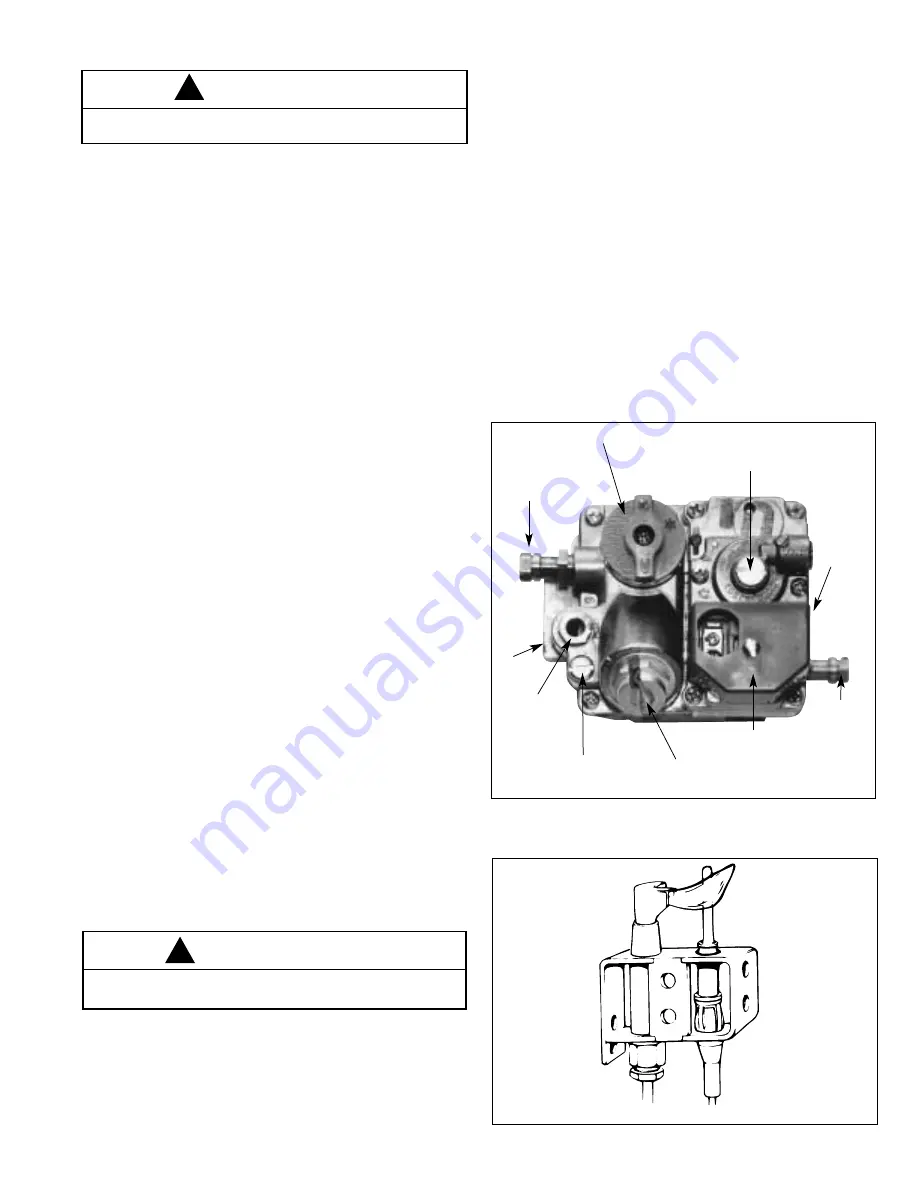
combination gas control (for location, see Figure 4).
If the pilot flame is longer and larger than shown by Figure
5 it is possible that this will cause soot and/or impinge on
the heat exchanger causing burnout. If the pilot flame is
shorter than shown it may cause poor ignition and result in
the controls not opening the combination gas control. A
short flame can be caused by a dirty pilot injector. Pilot
flame condition should be observed periodically to ensure
trouble free operation.
3.2.4. Move gas control knob to ON.
3.2.5. Set room thermostat to desired setting.
3.2.6. Check gas piping for leaks as described in IM 5.
3.2.7. Check gas input rate by measuring burner pressure using
the manometer fitted to test point at the outlet of the
combination gas control. Allow unit to operate for 15
minutes to stabilize. Check the pressure and if necessary
adjust to the figure shown in Table 2 on page 4 for the
particular model. The location of the pressure setting
adjuster on the combination gas is shown in Figure 4.
Remove the dust cover over the adjuster and, using a
small screwdriver turn the screw beneath clockwise to
increase and anti-clockwise to decrease the pressure.
Allow the unit to operate for 15 minutes then check the
pressure again. Replace the dust cover when finished.
Disconnect the manometer from the test point and replace
the sealing screw in the pressure test nipple.
3
3..3
3 C
Co
on
nttrro
oll O
Op
pe
erra
attiin
ng
g S
Se
eq
qu
ue
en
nc
ce
e
With pilot alight, when the thermostat calls for heat, power is
supplied to the combination gas control and at the same time
power is supplied to the fan timer. The main burner should light
immediately. The fan motor will start in 15 to 45 seconds. When
the thermostat has been satisfied, power is turned off to the
combination gas control and fan timer. The main burner will go
out but the pilot will continue to burn. The fan motor will continue
to operate for 45 to 75 seconds to allow the heat exchanger to
cool down.
F
Fiig
gu
urre
e 5
5
P
Piillo
ott F
Flla
am
me
e A
Ad
djju
us
sttm
me
en
ntt
3
3.. C
CO
OM
MM
MIIS
SS
SIIO
ON
NIIN
NG
G
F
Fiig
gu
urre
e 4
4
C
Co
om
mb
biin
na
attiio
on
n G
Ga
as
s C
Co
on
nttrro
oll
20/25mm
CAUTION
Start-up and adjustment procedures should be performed by
a qualified engineer.
!
CAUTION
Important – Supply pressure and setting pressure must be
checked with heater in operation when making final adjustments.
!
GAS CONTROL KNOB
INLET PRESSURE
TEST FITTING
PRESSURE REGULATOR
ADJUSTMENT SCREW
(UNDER CAP SCREW)
INLET
PILOT TUBING
PILOT ADJUSTMENT
SCREW
THERMOCOUPLE / INTERRUPTER
CONNECTION
PROTECTIVE COVER
OUTLET
OUTLET
PRESSURE
TEST
FITTING


