


5
5
Safe, efficient and trouble free operation of conventionally flued
appliances is vitally dependent on the provision of an adequate
supply of fresh air to the room in which the appliance is installed.
In buildings having a design air change rate of less than 0.5/h,
and where indirect fired heaters are to be installed in heated
spaces having volume less than:
(a) 4.7 m
3
per kilowatt of total rated heat input for heaters
fitted with natural draught burners: or
(b) 2.2 m
3
per kilowatt of total rated heat input for heaters
fitted with forced or induced draught burners;
grilles shall be provided at low level (i.e. below the level
of the appliance flue connection); except that:
(1) for heaters of heat input less than 60 kW, the total
minimum free area shall be not less than 4.5 cm
2
per
kilowatt of rated heat input; or
(2) for heaters of heat input 60 kW or more, the total mini-
mum free area shall not be less than 270 cm
2
plus 2.25
cm
2
per kilowatt in excess of 60 kW rated heat input.
Most traditional building constructions will provide air changes
of at least 0.5/h without the need for ventilation openings. In the
case of a building having an air change rate less than 0.5/h, low
level ventilation will be necessary.
For indirect heaters installed in buildings with a design air
change rate of 0.5/h or greater, and where the volume of the
heated space is greater than 4.7 m
3
per kilowatt of total rated
heat input, as appropriate, additional high and low level
ventilation will not be required.
2
2..3
3 U
Un
niitt S
Su
us
sp
pe
en
ns
siio
on
n
The most common method of hanging PDE unit heaters is to
utilize M10 threaded rod. On each piece of threaded rod used,
screw a nut about 25mm onto the end of the rods that will be
screwed into the unit heater. Then put a washer over the end of
the threaded rod and screw the rod at least 5 turns, and no
more than 10 turns, into the weld nuts on the top of the heater.
Tighten the nut first installed onto the threaded rod to prevent it
from turning. Drill holes into a steel channel or angle iron at the
same centreline dimensions as the heater that is being installed.
The steel channels or angle iron pieces need to span and be
fastened to appropriate structural members. Cut the threaded
rods to the preferred length, push them through the holes in the
steel channel or angle iron and secure with washers and lock
nuts or lock washers and nuts. A double nut arrangement can be
used here instead of at the unit heater (a double nut can be
used at both places but is not necessary). The entire means of
suspension must be adequate to support the weight of the unit
(see page 3 for unit weights).
For proper operation, the unit must be installed in a level
horizontal position. Clearances to combustibles as specified
below must be strictly maintained. The heaters must not be
installed above the maximum mounting height shown in Table 2
on page 4.
On all units, except the PDE 350 and PDE 400, two M10
tapped holes are located in the top of the unit to receive
threaded rods.
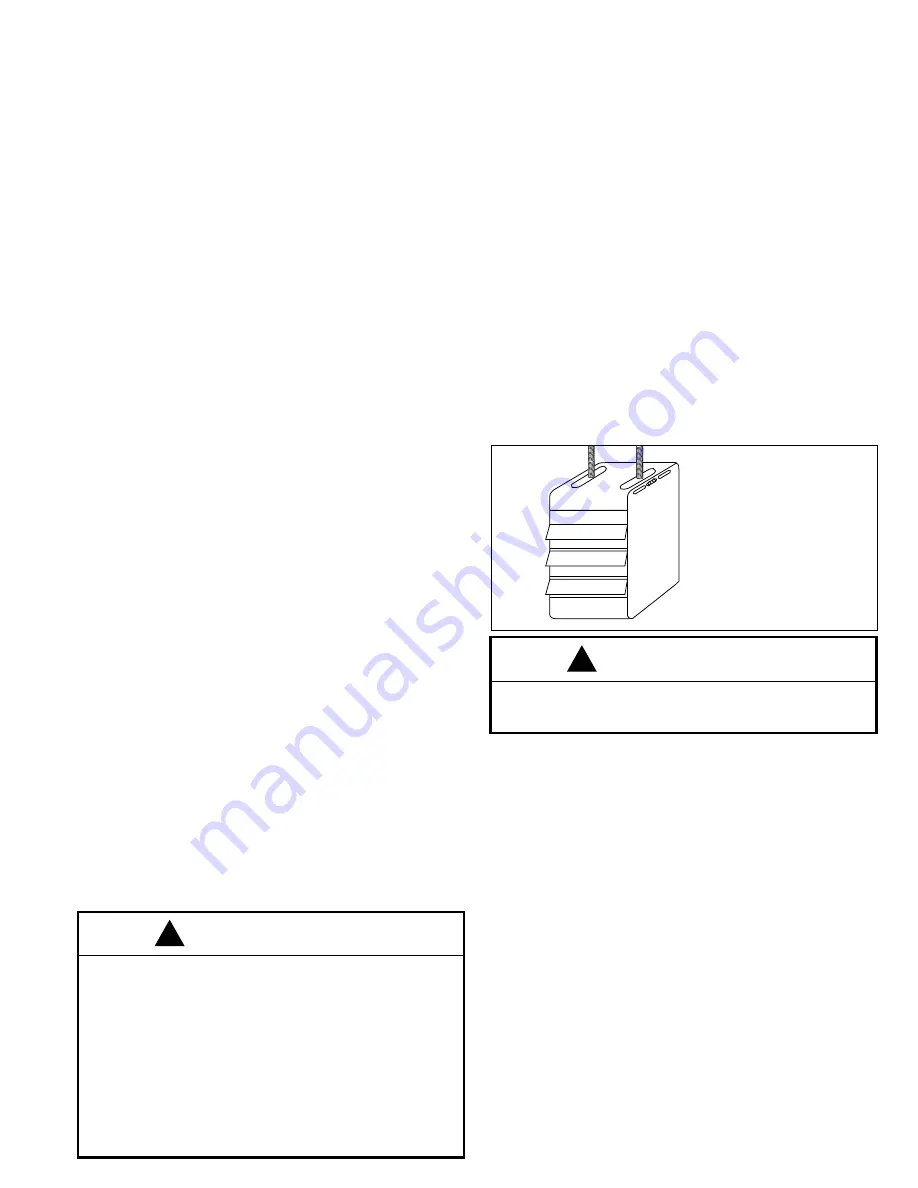
Units with two point suspension, models PDE30 to PDE300,
incorporate a level hanging feature.
PDE30 to PDE300 units that do not hang level after being
installed, can be corrected in place. Remove both outer side
panels (screws are on back flange of side panel) exposing the
(adjustable) mounting brackets (Fig.2). Loosen the set screws
holding the mounting brackets in place and using a rubber
mallet or something similar, tap the heater into a position where
it does hang level. Tighten set screws and replace the outer
side panels.
The PDE 350 and PDE 400 have four mounting holes in the top
of the unit.
T
To
o e
en
ns
su
urre
e tth
ha
att fflla
am
me
es
s a
arre
e d
diirre
ec
ctte
ed
d iin
ntto
o tth
he
e c
ce
en
nttrre
e o
off tth
he
e h
he
ea
att
e
ex
xc
ch
ha
an
ng
ge
err ttu
ub
be
es
s,, tth
he
e u
un
niitt m
mu
us
stt b
be
e s
su
up
pp
po
orrtte
ed
d iin
n a
a v
ve
errttiic
ca
all
p
po
os
siittiio
on
n,, w
wiitth
h s
su
us
sp
pe
en
ns
siio
on
n h
ha
an
ng
ge
errs
s ““U
UP
P””..
C
Ch
he
ec
ck
k w
wiitth
h a
a lle
ev
ve
ell..
This is important to the operation and life of the unit.
2
2..4
4 F
Fllu
ue
e S
Sy
ys
stte
em
m
To ensure safe and satisfactory operation of the heater, the flue
system must be capable of the complete evacuation of flue
products at all times. The height of the flue terminal above the
draught diverter must be at least 2m and for this height no more
than 0.6m horizontal run may be installed immediately after the
appliance outlet. For greater heights 0.3m horizontal run may be
added for each extra metre of flue height.
The chimney must terminate in a downdraught free zone.
Compliance with the recommendations made in BS.6644;
British Gas publication IMII Flues for Commercial and Industrial
Gas fired boilers and gas heaters’ and the ‘Third Edition of the
1956 Clean Air Memorandum’ should be strictly observed
where applicable.
The flue/chimney design should avoid the formation of excessive
quantities of condensate and for this reason it is recommended
that all chimneys are suitably insulated and lined.
Drain points should be fitted at the bottom of all vertical flue
sections. Drain pipes must be a minimum of 25mm internal
diameter and manufactured from acid condensate resistant
materials (e.g. stainless steel) and positioned so that pipe runs
and discharge points are not subject to the effects of frost and
that flue gases cannot leak into the room.
Any terminal fitted must be an approved type.
2
2..2
2 V
Ve
en
nttiilla
attiio
on
n
CAUTION
For all sizes, required minimum clearance to combustible
materials from the bottom of the unit is 300mm (but see
2.1.16) and from the sides 450mm. For PDE units sizes
30-50 minimum clearance from the top is 25mm and from
the flue collar 50mm; for PDE units sizes 75-300 minimum
clearance from the top is 50mm and from the flue collar is
75mm; for PDE unit 350 minimum clearance from the top is
75mm and from the flue collar is 100mm; for PDE unit 400
minimum clearance from the top is 100mm and from the flue
collar is 125mm. Allow at least 300mm clearance at the rear
or 150mm beyond the end of motor (whichever is greater) to
provide sufficient air for combustion and correct operation of
the fan. Provide clearance for opening at the hinged bottom
for servicing. See Figure. 1.
!
F
Fiig
gu
urre
e 2
2
A
Ad
djju
us
stta
ab
blle
e M
Mo
ou
un
nttiin
ng
g B
Brra
ac
ck
ke
etts
s
Remove side panels to adjust
mounting brackets
CAUTION
PDE unit heaters must be flued to outside – do not operate
without a flue. A built in draught diverter is fitted – additional
external draught diverters are not required or permitted.
!


