


www.mo-sys.com
5
Quick start guide and geometry alignment
This guide is only meant to serve as an
introduction and is not definitive. There are
many ways to set up the system and this is
only one of them.
First steps on both
XR Engine
and
Primary render node
1. Install or verify VP Free is updated to the
latest version on every computer:
https://www.unrealengine.com/marketpl
ace/en-US/product/mo-sys-tracking
2. Install the plugin on XR Engine and the
Primary Render Node. (pages 1-4 in
doc)
3. Configure livelink preset (page 8 in
Prepare
We assume the StarTracker is already
setup, auto-aligned and the lens is fully
calibrated! Refer to StarTracker manual
if that is not clear.
It is a crucial task to find a transform
(position, rotation and scale) of the LED
screen(s) in relation to the tracking
coordinate system, as it is used for
rendering the correct perspective on the
screens.
When working with set extension this is
even more pronounced, as the transition
between the graphics visible through a
camera and the extended by XR engine
must be seamless.
The layout of screen(s) geometry will be
used on both the XR Engine to mask the
LEDs and the rendering nodes to define the
nDisplay configuration.
New UE project
Let’s
start on the XR Engine. Create a new
empty UE project. Once successfully
installed the plugin, make sure the following
steps are completed (pages 12-13):
•
VP Pro project settings are set to the
correct framerate, HasTimecodeSync is
unchecked and compositing mode is set
to XR
•
Video input is coming to the engine
•
Livelink preset is set up for getting
tracking data
Open
AligningXR
level, which can be found in
/MoSysVPPro/Content/Compositing/XR/Alig
nment
Pilot the camera to get the composite view.
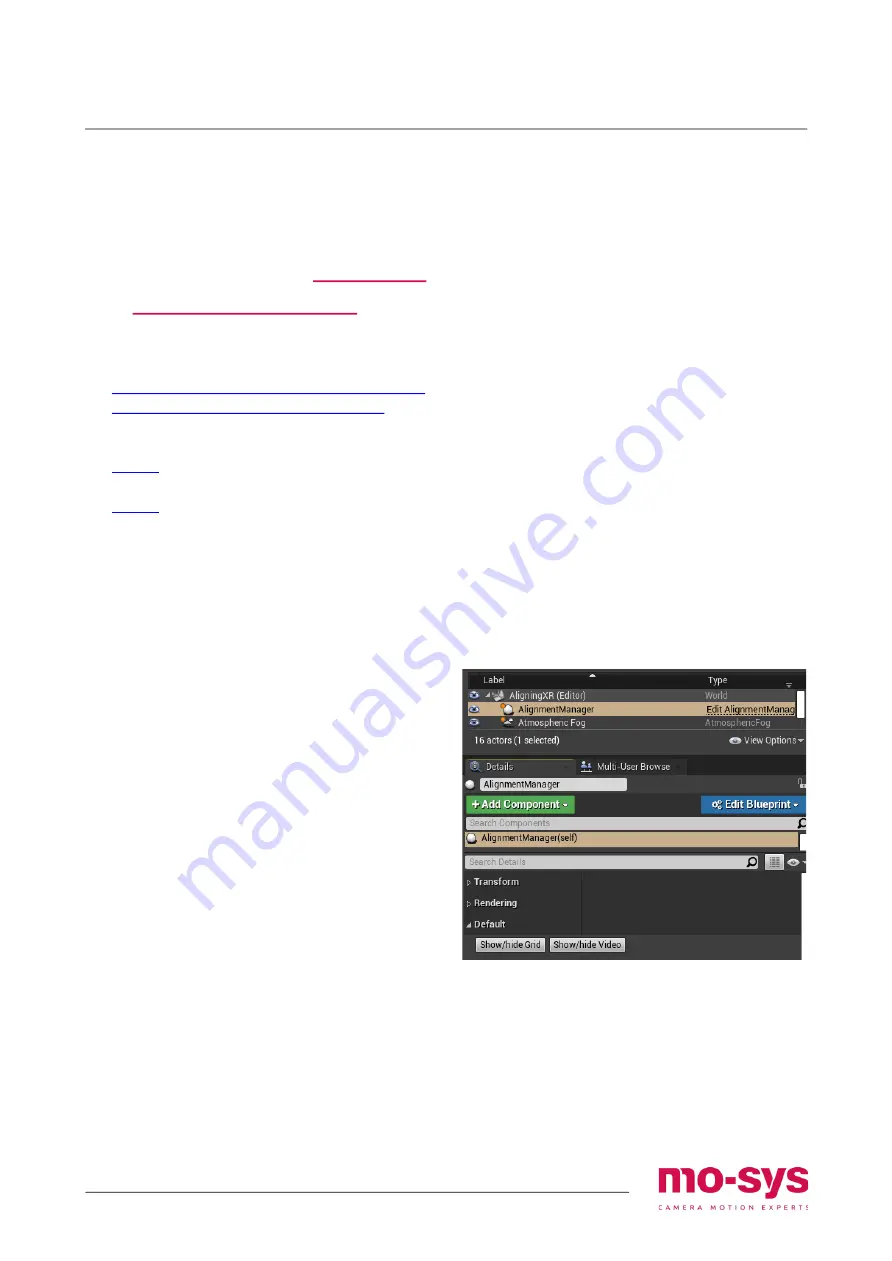
Use
Alignment manager
actor to toggle
visibility of the grid and to show video only.
If the camera image
doesn’t
show up then in
MoSysCameraXR
details select the input
texture to provide the video feed under
VideoInput -> Input Texture.
Geometry alignment
For the purpose of the next steps
hide the
grid
and
show video
, so there is a feedback
as to where the camera is looking at.
Depending on the shape of the LED
screen/volume the alignment procedure will
vary. If there is just a flat, rectangular wall or
multiple of these then the Mo-Sys
Mesh
Builder
panel can put the geometry in
place. First, we will use it to verify the ST and
lens calibration. Go to page 15 for the
details of Mesh Builder.


