


You may finish calibration without changing the active channel by pressing ESC. The
calibration of other channels which have been changed before remains stored.
Enter a sensor name with up to 20 characters using the ◄▲▼► keys and confirm with OK.
The VM30-H may store the sensitivities of two transducers. You may check the entered values
anytime when you open the menu “7/8: Sensor”, choose “Edit this sensor?“, confirm the
nominal sensitivity by OK and choose “By transducer sensitivity”. If you do not want to change
the calibration values, only press the OK key.
15.3. Mechanical Calibration
Mechanical calibration may be used to check the accuracy of the complete measuring chain of
accelerometer and VM30-H. The following calibration procedure requires that the sensitivities
of the used transducer have been entered correctly as shown above.
For mechanical calibration the transducer is mounted successively in the three directions onto
an electrodynamic shaker. For mounting accessories, please contact Metra.
Calibration is performed at a reference signal of 5 m/s² (RMS) / 80 Hz for hand-arm sensors and
at 0.5 m/s² / 16 Hz for whole-body sensors. At the VM30-H the filter 0.4 Hz – 100 Hz or 10 –
1250 Hz is selected. The following table shows the vibration levels and VM30-H settings for
mechanical calibration:
Channel
Shaker Signal
Level (RMS) Frequency
Settings at VM30-H
Typical display values (m/s²)
X
Y
Z
Max.
Error
Calibration with hand-arm accelerometer (nominal sensitivity 1 mV/ms
-2
):
X
50 m/s²
80 Hz
10-1250 Hz, a, A(T), 120 m/s²
50.0
0
0
4 %
Y
50 m/s²
80 Hz
10-1250 Hz, a, A(T), 120 m/s²
0
50.0
0
4 %
Z
50 m/s²
80 Hz
10-1250 Hz, a, A(T), 120 m/s²
0
0
50.0
4 %
Calibration with whole-body accelerometer (nominal sensitivity 10 mV/ms
-2
):
X
5 m/s²
16 Hz
0.4-100 Hz, a, A(T), 12 m/s²
5.00
0
0
4 %
Y
5 m/s²
16 Hz
0.4-100 Hz, a, A(T), 12 m/s²
0
5.00
0
4 %
Z
5 m/s²
16 Hz
0.4-100 Hz, a, A(T), 12 m/s²
0
0
5.00
4 %
15.4. Electrical Calibration
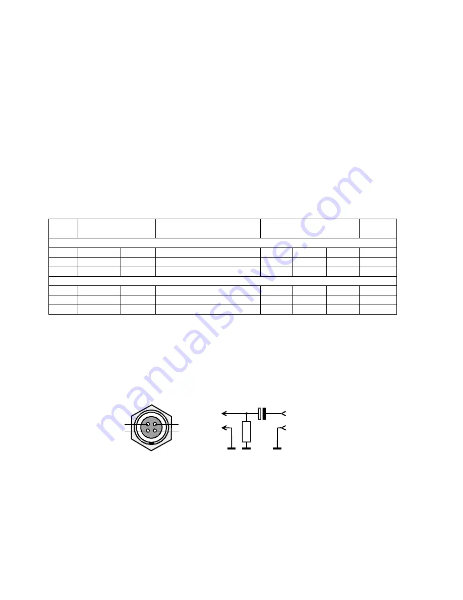
The VM30-H can be calibrated without the sensor by means of an electrical generator signal.
Since the inputs are equipped with constant current sources, RC coupling circuits must be
connected between the VM30-H and the generator. Figure 27 shows the the required
components and the pin assignment of the input socket.
The 10 kΩ resistor is necessary to sink the constant current. The voltage drop is approximately
10 V. This DC voltage is decoupled from the generator output by a 100 µF electrolytic
capacitor. The capacitor should be rated for at least 35 V. Please make sure that the generator
output is not affected by a load of approximately 3 kΩ.
The following table shows the steps which are performed by factory calibration and the
corresponding generator signals. The shown values are based on an entered transducer
sensitivity of 10 mV/ms
-2
.
40
Figure 27: Connecting the VM30-H inputs to a generator
GND
X
Y
Z
+
4k7
1000µ
Generator
GND
X/Y/Z
Содержание VM30-H
Страница 5: ...25 Technical Data 50 Appendix Warranty Declaration of Conformity...
Страница 40: ...35...