OPERATOR MANUAL
EXLRT
Ref: XLR-104
© 2020 MK Test Systems Ltd
Page 22 of 28
Taking a measurement
Loop Test
During the loop test, the loop inline controller and the ExLRT front panel indicator will illuminate
amber for the duration of the loop test. If an error has occurred during the loop test, the in-line
controller and ExLRT front panel indicator will flash red with the error condition printed on the LCD
screen.
To clear the screen, initiate a loop or joint test.
Joint Test
After the joint test has been initiated by connecting the joint probes to the UUT, the ExLRT will
automatically start taking a loop and joint measurement. All ExLRT and cable indicators will illuminate
amber for the duration of the test. After the test, the ExLRT will display the valid measurements.
After the joint test the ExLRT will re-start the joint process (probe green LED flashing).
If a joint error was detected, the joint probe red LED will flash until the user clears the error by
pressing the green button again. This will return to waiting for another joint test to commence
(flashing green)
If a loop error was detected, the loop in-line controller red LED will be flashing until the user clears
the error by pressing either the green button on the in-line controller or the green button on the joint
probe.
Exit from single shot mode
Ensure that both ExLRT front panel test status indicators are turned off and press the back
button to exit out of the manual mode and return to the main menu
12
S
TRAY CURRENT
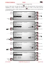
To perform a stray current measurement, simply connect the MK52 Sense Coupler to the loop and
navigate into the Stray Current Measurement
This will give you a magnitude (in current) of induced current in the loop
Содержание ExLRT
Страница 1: ......


