background image

OPERATOR MANUAL 

EXLRT 

Ref: XLR-104 

© 2020 MK Test Systems Ltd


Page 19 of 28 


Averaging 

Averaging applies to both the loop and joint measurements and can only be enabled and disabled 

when the ExLRT is not taking measurements. 

Averaging ON 

With averaging on, the following icon is displayed 

Averaging the loop and joint measurements is implemented by taking the first valid sample of the 

measurement  then  applying  a  sum  over  count  method.  The  start  of  averaging  occurs  under  the 
following conditions: 

1)


Start of continuous mode 

2)


Any change of state 

3)


After an error condition 

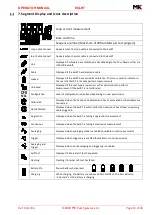
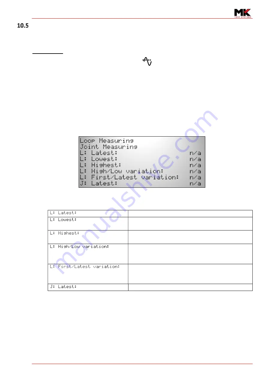
During continuous mode measurements with averaging enabled, the following will be shown in the 

dot matrix area. 


If the joint probes are not connected 

J: Latest:


will not appear. 

Below is a description of the values displayed on the screen  

Latest loop resistance calculated 
Lowest resistance recorded since commencing 

continuous mode, last error or change of state 
Highest resistance recorded since commencing 

continuous mode, last error or change of state 
Difference (or pk-pk) between the last recorded 

highest and lowest measurements since commencing 

continuous mode, last error or change of state 
Difference between the first measurement at the 

start of continuous/last error or change of state to the 

latest measurement 
Latest Joint resistance (if joint cable connected) 


Содержание ExLRT

Страница 1: ......

Страница 2: ...T Ref XLR 104 2020 MK Test Systems Ltd Page 2 of 28 OPERATOR MANUAL EXLRT XLR 104 1 Author Giuseppe Prisco Date 12th December 2019 Reviewed Jamie Spiller Date 5th February 2020 Approved Alan Wilson Da...

Страница 3: ...g out of the use of the information contained within this safety manual The information contained within the safety manual is the property of MK Test Systems Ltd and reproduction in whole or part shal...

Страница 4: ...Manual Menu 16 Manual measurement modes 17 Overview 17 10 Continuous mode measurements 18 Starting Continuous 18 Pausing continuous mode measurements 18 Resuming continuous mode 18 Exiting from conti...

Страница 5: ...understand the operation of the ExLRT and its associated components This manual does not include safety information for the ExLRT Refer to document XLR 927 Do not operate the ExLRT without reading an...

Страница 6: ...easure the bond joints within the loops The ExLRT uses current couplers that non intrusively couple an AC signal into the loop A drive coupler is used to inject the signal with a known voltage and a s...

Страница 7: ...04 2020 MK Test Systems Ltd Page 7 of 28 ExLRT Overview Power input Joint Connector Power on button USB Connector Loop Connector LCD Display Joint status indicator Loop status indicator Battery compar...

Страница 8: ...joint measurements The indicators act as repeaters to the LEDs situated on the Loop and Joint cables The indicator colours identify the following test status Loop status indication Joint status indic...

Страница 9: ...LED states to indicate the state of the battery Charger State Normal working condition LED 1 Left LED 2 Right Ready to Charge Battery not installed Off Green Charging Red Green Battery Inserted and fu...

Страница 10: ...permissions Once the verification is performed and the ExLRT has passed the ExLRT and will display the icon when the correct combination of cables are connected to the ExLRT Calibration Warning Date...

Страница 11: ...e used as calibrated The designed nominal value is 9 5m but expect to see small deviations in measurement for each ExLRT manufactured MK does not hold itself responsible if the Self Test Loop yields a...

Страница 12: ...Supports multiple users Login using user ID and Password Up to 32 users Setup with permissions restrictions Up to 15 user configurations one allocated for Customer Administrator Icons showing the fol...

Страница 13: ...not calibrated Configuration Level of configuration is displayed depending on user permissions Calibrated Displayed when the has been Calibrated and has its associated verified cables are connected N...

Страница 14: ...straight to the ExLRT main menu See section 8 Main Menu See document XLR 105 Section ExLRT Device Settings to how to configure Log On Enter User ID If login is enabled at start up then the ExLRT will...

Страница 15: ...he device Proceed to measurement screen Press the to proceed straight to the measurement screen If manual mode is set to Continuous go to section 10 Continuous mode measurements If manual mode is set...

Страница 16: ...select See section To operate in single shot mode use the up down buttons to highlight Single shot then press the select button See section 11 Single Shot Operating the ExLRT temporarily in the non d...

Страница 17: ...two decimal places If the joint measurement is not valid the ExLRT will null the 7 segment display and show a description of the error on the dot matrix display Joint measurements A joint measurement...

Страница 18: ...ements To take a joint measurement simply connect the joint probes to the UUT Pausing continuous mode measurements To halt continuous mode measurements press any of the red buttons on the in line cont...

Страница 19: ...n During continuous mode measurements with averaging enabled the following will be shown in the dot matrix area If the joint probes are not connected J Latest will not appear Below is a description of...

Страница 20: ...ger on Resistance Limits Both methods can be enabled at the same time or either method can be applied individually The use of triggering is to primarily fault find suspect loops The ExLRT triggering f...

Страница 21: ...op cable green LED flashing Joint probe green LED flashing Press the green button on the In Line controller This will perform a loop only test Joint indicator and data is cleared When the test stops t...

Страница 22: ...he valid measurements After the joint test the ExLRT will re start the joint process probe green LED flashing If a joint error was detected the joint probe red LED will flash until the user clears the...

Страница 23: ...roll buttons to highlight the option then press the select button to enter the selected menu 14 EXLRT UNIT 15 CABLE Entering this screen will provide live information of the connected cables As an exa...

Страница 24: ...f 28 16 CALIBRATION INFORMATION 17 SETTINGS MENU Go to section 18 to enter the Measurement menu Go to section 19to enter the Calibration menu Go to section 20to enter the Settings menu Select Go back...

Страница 25: ...he configuration at the time of logging in Use the scroll buttons to highlight the desired option then press the button to go to the value Once the value has been highlighted press the button to toggl...

Страница 26: ...the Change Trigger Limits screen Toggle to to turn triggering off default when entering this screen Change of reading To change the value press the select button to enter the change value window Chan...

Страница 27: ...n in 1m steps using the increase decrease buttons When finished press the button to move on to the decimal place part of the resistance No Action Increase value Go to lower Go back to listing Decrease...

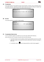
Страница 28: ...der to use this function 20 SYSTEM This window displays any specific hardware setting 21 CALIBRATION VERIFICATION To run a verification program the ExLRT must be controlled via MK ExLRT PC Software Af...

Отзывы: