background image

1 - 2

No. 99MBC034B

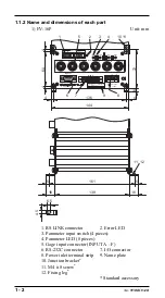
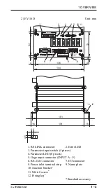
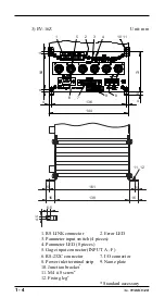
1.1.2 Name and dimensions of each part

1) EV-16P

Unit: mm

11

10

9

8

7

6

5

4

3

2

1

Code No.***-***

Model EV-16P

Code No.***-***

MADE IN JAPAN

RS LINK

Err.

OUT

IN

LOAD

8 7

MODE

6

5

4

3

SEL.

2 1

DATA

F

E

D

INPUT

C

B

A

RS-232C

IO/BCD

+V

-V

DC12-24V

700mA

144

6

72

4

4

136

4

4

64

11, 12

4.5

6.5

16

16

139

5

5

161

1. RS LINK connector

2. Error LED

3. Parameter input switch (4 pieces)
4. Parameter LED (8 pieces)
5. Gage input connector (INPUT A - F)
6. RS-232C connector

7. I/O connector

8. Power inlet terminal strip

9. Name plate

10. Junction bracket

*

11. M4 

x

 8 screw

*

12. Fixing leg

*

* Standard accessory

Содержание EV Counter

Страница 1: ...1234567890123456789012345678901212345678901234567890123456789012123456 1234567890123456789012345678901212345678901234567890123456789012123456 123456789012345678901234567890121234567890123456789012345...

Страница 2: ...h Indicates a potentially hazardous situation which if not avoided could result in serious injury or death Indicates a potentially hazardous situation which if not avoided may result in minor or moder...

Страница 3: ...e emphasizes or supplements important points of the main text A note supplies information that may only apply in special cases e g Memory limitations equipment configura tions or details that apply to...

Страница 4: ...t up or operating it Use this counter in an environment where the temperature is between 0 C and 40 C The temperature variation should be minimized so there is no condensation Avoid operating this cou...

Страница 5: ...written consent of Mitutoyo or as a result of damage by an actual disaster or circumstances beyond the control of Mitutoyo To obtain service under this warranty the product must be returned to the nea...

Страница 6: ...2 2 1 Connecting gages 2 2 2 2 2 Connecting the D EV External Display Unit 2 3 2 2 3 RS 232C I O BCD and RS LINK connections 2 3 2 2 4 Connecting the power supply and grounding 2 3 2 3 Power On 2 4 3...

Страница 7: ...Pin assignment 5 2 5 2 4 List of available commands 5 2 5 2 5 RS 232C command and RS 232C response output 5 5 5 2 6 HOLD input and RS 232C response output 5 5 5 2 7 Time required for RS 232C data outp...

Страница 8: ...wer ON characteristics 7 14 7 7 2 Output period of tolerance judgment result 7 14 7 7 3 Data output 7 15 7 7 4 External presetting 7 16 7 7 5 Designating CELs to be output Specifying the calculation m...

Страница 9: ...xample a personal computer The display unit is of a separate type optional which takes in line use into consideration Depending on the external devices to be connected and uses the fol lowing I F conn...

Страница 10: ...1 DATA F E D INPUT C B A RS 232C IO BCD V V DC12 24V 700mA 144 6 72 4 4 136 4 4 64 11 12 4 5 6 5 16 16 139 5 5 161 1 RS LINK connector 2 Error LED 3 Parameter input switch 4 pieces 4 Parameter LED 8...

Страница 11: ...00mA 144 6 72 4 4 136 4 4 64 F E D C B A INPUT 11 10 9 8 7 6 4 3 2 1 D 11 12 4 5 6 5 16 16 139 5 5 161 1 RS LINK connector 2 Error LED 3 Parameter input switch 4 pieces 4 Parameter LED 8 pieces 5 Gage...

Страница 12: ...6 5 16 16 139 5 5 161 1 RS LINK connector 2 Error LED 3 Parameter input switch 4 pieces 4 Parameter LED 8 pieces 5 Gage input connector INPUT A F 6 RS 232C connector 7 I O connector 8 Power inlet term...

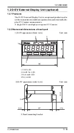
Страница 13: ...arameters and externally dis play EV Counter measurements A single D EV can display set up one EV Counter 1 2 2 Name and dimensions of each part 1 D EV appearance front view Unit mm 4 2 3 1 MODE P SET...

Страница 14: ...MBC034B 3 D EV appearance rear view Unit mm 6 8 7 000001 D EV 02ADD400 MADE IN JAPAN Serial No Model Code No V V 200mA DC12 24V OUT IN RS LINK 91 4 6 RS LINK connector 7 Name plate 8 Power inlet termi...

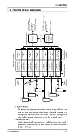
Страница 15: ...1 CEL2 CEL3 CEL4 CEL5 CEL6 CEL designation Peak mode switching Zero setting Presetting Peak clear Tolerance value input I O output Tolerance judgment output Segment output BCD output CEL designation C...

Страница 16: ...alculation func tion Therefore calculation can be performed between the counters specified by the parameters Output function Either RS 232C BCD tolerance judgment or segment out put can be selected Th...

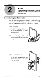
Страница 17: ...come as the standard accessories to install the EV Counter a The fixing legs 1 Attach the fixing legs 4 places on the counter main unit using the supplied screws 2 Use the oval hole provided on each f...

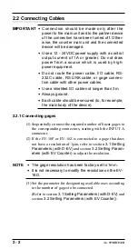
Страница 18: ...ays ground Each cable should be secured to for example the main body of the device 2 2 1 Connecting gages 1 Sequentially connect the required number of linear gages to the corresponding connectors sta...

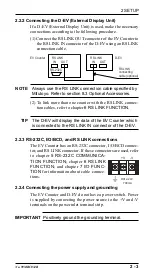
Страница 19: ...unter with the RS LINK connec tion cables refer to chapter 6 RS LINK FUNCTION TIP The D EV will display the data of the EV Counter which is connected to the RS LINK IN connector of the D EV 2 2 3 RS 2...

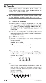
Страница 20: ...NICATION FUNCTION and chapter 7 I O FUNCTION 2 If the EV 16Z is used push in the spindles of all connected gages to pass through the origins after completing the proce dure 1 described above b If a D...

Страница 21: ...the spindle through the origin for detection properly If the spindle vibrates near the origin the origin may not be detected correctly TIP The origin embedded gage has a specific origin in side the ga...

Страница 22: ......

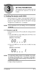
Страница 23: ...solution of 0 1 m setting a D EV is absolutely necessary 3 1 1 Parameter mode ON Set the parameter mode to ON to modify the existing parameter settings 1 Press the P SET key while holding down the Fn...

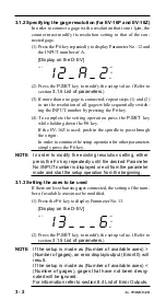
Страница 24: ...h the origin In order to continue the setup operation for other parameters simply press the Fn key NOTE In order to modify the existing resolution setting either press the Fn key repeatedly until the...

Страница 25: ...D INPUT E INPUT A 6 2 INPUT A INPUT B INPUT C INPUT D INPUT E INPUT F 1 If the setup value is 2 internal counters CEL1 3 and 5 will display output the data of INPUT A Internal counters CEL2 4 and 6 wi...

Страница 26: ...ries Specification of gage type 1 ABS LGD series 2 ABS ORG 13 Designation of available 6 6 gages are used axes 2 5 5 gages are used 4 4 gages are used 3 3 gages are used 2 2 gages are used 1 1 gage is...

Страница 27: ...page 3 3 3 This is not modified even if an attempt is made to clear the parameters If the display unit is set to E the UNIT LED lights in green 4 Sets the CEL to be used for the calculation function...

Страница 28: ...is not possible Only a D EV allows setting when the modification is made for the parameter no 41 42 and 43 In order to connect a gage with a resolution that is not 1 m the counter must modify its reso...

Страница 29: ...n of LEDs No 1 and 2 will change Parameter LED Indicator 2 1 DATA 2 1 DATA 2 1 DATA 2 1 DATA 3 Accept the parameter value selected by pressing the LOAD button The next parameter for setup is automatic...

Страница 30: ...5 m Resolution of INPUT E 1 Resolution of INPUT F 1 Case of EV 16D Gage type of INPUT A INC LGS series Gage type of INPUT B Gage type of INPUT C ABS LGD series Gage type of INPUT D Gage type of INPUT...

Страница 31: ...L1 2 CEL1 2 3 CEL1 2 3 4 All CELs 5 I O output mode 6 Command Interval I O output logic 7 Output terminal is H Output terminal is L Selection of I O function 6 NORMAL mode Calculation mode High speed...

Страница 32: ...lculation the available axes 6 1 2 3 4 5 6 5 1 2 3 4 5 4 1 2 3 4 3 1 2 3 2 or 1 1 2 6 For information about this function refer to chapter 7 I O FUNCTION 7 The output logic of the data section will va...

Страница 33: ...by referring to section 2 3 Power On Neither move the gage stylus nor operate any key until the EV Counter enters the counting stand by state Counting stand by state on D EV UNIT NG GO NG 4 BASIC OPER...

Страница 34: ...counter is connected it is assigned CH numbers 01 through 06 which corresponds to CEL1 through CEL6 For more information refer to chapter 5 RS LINK FUNCTION GAGE No LEDs show the currently displayed C...

Страница 35: ...dg ment results from CEL1 to CEL6 at the same time Indication of GAGE No LED GAGE Display on D EV UNIT NG CEL1 CEL2 CEL3 CEL4 CEL5 CEL6 GO NG NOTE While the bar is being displayed only the DISP key ca...

Страница 36: ...The count value of the selected CEL will be displayed on the D EV or output 2 Press the MODE key to switch the peak mode The on off pattern of the LEDs on the D EV shows the selected peak mode MAX MIN...

Страница 37: ...d mode Refer to section 4 3 Switching the Peak Mode with D EV 3 Press the P SET key to clear the peak value This results in Max Min Current value and TIR 0 NOTE If the P SET key is pressed in the curr...

Страница 38: ...Lower tolerance limit GAGE amber Upper tolerance limit GAGE red Display on the D EV current value display UNIT NG GO NG NOTE The D EV Counter uses a 6 digit display however a value consisting of a ma...

Страница 39: ...set values and tolerance values are retained in memory even when the power is off Set a lower tolerance limit that is equal to or smaller than the upper tolerance limit An incorrect setting may cause...

Страница 40: ...following procedures 1 Press the DISP key to select a CEL number in the error state Then press P SET key 2 The HOLD input signal rises to H I O 3 Input the CS command RS 232C NOTE While the error stat...

Страница 41: ...Current value and TIR 0 NOTE The EV Counter can count a maximum of eight digits however the D EV Counter can display a maximum of six digits If a number has more than six digits the most significant...

Страница 42: ...the peak modes Max Min and TIR The GAGE No LED s on pattern indicating the selected CEL number will light in a different color ac cording to the tolerance judgment result Display example of tolerance...

Страница 43: ...fication D sub 9 pin male inch screw specification Applicable plug specification D sub 9 pin female inch screw specification Examples of commercially available cables DOS V KRS 403XF 1K 1 5m Manufactu...

Страница 44: ...Switches to the max value display CM CRLF CH CRLF Switches to the min value display CW CRLF CH CRLF Switches to the TIR display CR CRLF CH CRLF Zero sets CL CRLF CH CRLF Clears peak values CP CH CRLF...

Страница 45: ...es 02 08 13 Obtains each mean of specified axes 03 09 14 Obtains the max value of specified axes 04 10 15 Obtains the min value of specified axes 05 11 16 Obtains Max Min of specified axes If more tha...

Страница 46: ...ll be resumed To quit the counting stand by state use CS00CRLF all channels specification Note that the GA command and CT command look similar however their functions differ GA command Outputs the cou...

Страница 47: ...TIR measurement Response output NOTE During key operation RS 232C output will be sus pended and it will be resumed after the key operation has been completed If the RS LINK connection has been establi...

Страница 48: ...lable channels x 8 5 3 Transmission speed 9600bps 19200bps Example One EV 16P unit total 6 gage channels Max 118ms 64ms Ten EV 16P units total 60 gage channels Max 1126ms 610ms NOTE Number of connecte...

Страница 49: ...unter IN OUT RS LINK IN OUT RS LINK connection cable with a maximum length of 10 m 10 units maximum If one D EV is inserted in the middle as shown below it will display the data of EV Counter A D EV R...

Страница 50: ...er to all the EV Counters D EVs si multaneously or turn on the power sequentially starting from the top EV Counter D EV The initial setup will com mence During initial setup the D EV displays a flashi...

Страница 51: ...ting stand by state is displayed on the D EV while the power is being turned on 1 Is the RS LINK cable connected properly 2 If EF Counters are being used with EV Counters make sure that the Digimatic...

Страница 52: ...6 4 No 99MBC034B...

Страница 53: ...ch 36 pin female Plug 10136 3000VE Manufacturer 3M or equivalent Cover 10336 52A0 008 Manufacturer 3M or equivalent 7 3 Input Output Circuit 7 3 1 Output circuit Application Tolerance judgment output...

Страница 54: ...olerance judgment 3 Pin assignment 1 19 18 36 No Name I O Functional description 1 COM Common terminal of I O circuit 2 COM connected to internal GND 3 CEL1_ NG OUT Tolerance judgment result of CEL1 N...

Страница 55: ...DY OUT L if the output data has been accepted 29 START OUT L only when CEL1 data has been output 30 NORMAL OUT H at an anomaly Result of ORing NOMs of all CELs 31 P SET IN Presets the specified CELs 3...

Страница 56: ...o internal GND 3 1 100 OUT BCD output data 4 2 100 OUT 5 4 100 OUT 6 8 100 OUT 7 1 101 OUT 8 2 101 OUT 9 4 101 OUT 10 8 101 OUT 11 1 102 OUT 12 2 102 OUT 13 4 102 OUT 14 8 102 OUT 15 1 103 OUT 16 2 10...

Страница 57: ...origin if the pa rameter No 42 is set to 1 Outputs of No 3 through No 27 can be logically inverted by the I O output logic parameter Inputs of No 31 through No 36 are valid at L 4 Designating CELs to...

Страница 58: ...eg ment output 2 Parameter setups I O function selection parameter Set to NORMAL I O type selection parameter Set to segment output 3 Pin assignment 1 19 18 36 No Name I O Functional description 1 COM...

Страница 59: ...EL was input 35 SET3 IN In the NORMAL High speed mode CEL designation In the calculation mode Specification of calculation method 36 HOLD IN The display value is held during the input The error is cle...

Страница 60: ...2 0 01 1 0 1 0 5 0 2 5 0 0 5 0 0 25 0 5 0 25 0 05 0 025 1 1 0 0 10 1 0 5 0 5 0 1 0 1 0 0 5 0 05 1 1 1 0 20 2 0 10 1 0 2 0 2 0 1 0 1 List of measurement ranges If the peak mode is set to TIR SET SET SE...

Страница 61: ...Only the corresponding terminal Ln is ON MAX Corresponding terminals from L10 to Ln are ON MIN Corresponding terminals from Ln to L10 are ON TIR Only the corresponding terminal Ln is ON NOTE Output at...

Страница 62: ...0 H 1 L 7 5 2 Tolerance judgment result output 1 Function A tolerance judgment of the calculation result will be out put from CEL6 In case of no calculation a tolerance judgment to the count value of...

Страница 63: ...cases where SET 000 a tolerance judg ment will be output to the measured value of CH06 and the measured value will be displayed after CH06 F is displayed 7 5 3 BCD output 1 Function Outputs the calcu...

Страница 64: ...gh speed output of CEL6 data 1 1 1 Specification prohibited 0 H 1 L Other CEL output functions are disabled NOTE About operation during suspension Presetting peak clear or zero setting operation with...

Страница 65: ...to tolerance judgment output 7 6 3 BCD output 1 Function Quickly outputs the CEL data specified by output CEL des ignation as BCD data 2 Parameter setups I O function selection parameter Set to the h...

Страница 66: ...on last will be used as the reference 7 7 2 Output period of tolerance judgment result CEL outputs are not simultaneous Upper limit Lower limit Count data NG NG Max 35ms Max 10ms Max 90ms Max 35ms Max...

Страница 67: ...6ms 2ms CEL1 CEL2 CEL3 CEL4 CEL5 CEL6 While the HOLD signal is being input the UNIT LED on D EV will flash 2 Command mode for outputting individual CELs With synchronized control of the HOLD and READ...

Страница 68: ...tting individual CELs According to the internal timing of the counter the data of each CEL specified by SET1 through SET3 will be output sequentially READY Tolerance judgment segment BCD data 30ms 35m...

Страница 69: ...on 7 4 4 Segment output Operation varies depending on the setups of the I O function selection parameter NORMAL or high speed mode Output CEL designation Calculation mode Specification of calculation...

Страница 70: ...7 18 No 99MBC034B 7 7 7 HOLD timing...

Страница 71: ...1 m Maximum counting speed 5MHz Maximum input 1 25MHz two phase frequency square wave Response time depends on the gage to be used Power supply DC12V 24V 700mA from terminal voltage strip M3 screw Pow...

Страница 72: ...xternal Display Unit 02ADB440 Output connector with cover 02ADD950 RS LINK connection cable 0 5 m 936937 RS LINK connection cable 1 m 995014 RS LINK connection cable 2 m 02ADD930 Terminal strip connec...

Страница 73: ...H OV H H CEL _ NG L NOM H FFFF15 On in amber Error15 Counting stand by P SET key In the power is CEL _ NG L OV L lights On No display state when power CS00 command interrupted check CEL _NOM H OV L in...

Страница 74: ...e state state Off setup error tolerance value L Counting Counting F F No display Normal The count value Self cancellation Not required 8 state state Off output more than 6 digits L CEL _ NG L NOM H FF...

Страница 75: ...and displayed when the CH that caused the error is specified for output 3 Displayed if a tolerance setup error occurs due to a key operation 4 The error output format will be CH Error CRLF 5 Output if...

Страница 76: ...Printed in Japan Mitutoyo Corporation 20 1 Sakado 1 chome Takatsu ku Kawasaki Kanagawa 213 0012 Japan Cable MITUTOYO Kawasaki Phone 044 813 8230 Fax 044 813 8231...

Отзывы: