background image

1-21

Chapter 1  GENERAL

Crankshaft pulley

V-belt

32620-00300

Y

Y

Y

Y

Y

Y

Y

Y

Y

Y

Y

V-belt
32620-10500

Y

Ribbed belt
32620-01100

Y

Flywheel

Standard
(32621-00052)

Y

Y

Y

Y

Y

Y

Y

FCD

(32621-00080)

Y

Y

Y

Y

Damper

Single  damper

Y

Y

Y

Y

Y

Y

Y

Y

Y

Y

Y

Double damper

Y

Front pulley

(32625-54101)

Y

Y

Y

Y

(45685-60600)

Y

Y

Y

Y

Y

(32625-04301)

Y

(45120-90300)

Y

Y

Y

(32625-04801)

Y

Y

(32625-05901)

Y

(45125-97300)

Y

(32620-00700)

Y

Y

Fuel
injection nozzle

Screw adjust type
(32561-76050)

Y

Y

Y

Screw adjust type
(32561-64010)

Y

Y

Y

Y

Screw adjust type

(32561-79010)

Y

Y

Screw adjust type
(32561-54010)

Y

Y

Shim adjust type
(35A61-11030)

Y

Y

Y

Y

Shim adjust type

(32661-11070)

Y

Y

Shim adjust type
(32661-11060)

Y

Shim adjust type
(32661-01050)

Y

Y

Shim adjust type

(32661-01090)

Y

Fuel filter

Diesel oil
(32562-61010)

Y

Y

Y

Y

Y

Y

Diesel oil
(32562-60010)

Y

Y

Y

Y

Diesel oil, change 
over type

(37562-70800)

Y

Y

Y

Y

Wire element type
(04122-39001)

Y

Y

Y

Y

Y

Y

Y

Y

Y

Equipment name

Specification name

PT

A

PT

A

-S

PT

A

2

Y1PT

A

PT

A

W

Y2PT

A

W

-2

PTK

MPT

A

MPTK

C2

MPTK

MTK

Содержание S12A2

Страница 1: ...SERVICE MANUAL September 2010 Pub No 99269 20170 199269 20170 ...

Страница 2: ......

Страница 3: ...work of the engine and engine parts Read through this manual carefully and understand the work procedures fully before dis assembling inspecting repairing or assembling the engine The contents of this manual are based on the engine model produced at the time of publi cation Please note that the contents of this manual may change due to improvements made thereafter Cautions on emissions requirement...

Страница 4: ... a call out of part names listed in the text but also an indica tion of the sequence of disassembly 2 Inspections to be conducted during disassembly process are indicated in boxes in the relevant exploded views 3 Maintenance standards required for inspection and repair works are indicated in the appropriate positions in the text They are also collectively indicated in the Chapter 2 4 The tightenin...

Страница 5: ...Bottom Dead Center TIR Total Indicator Reading API American Petroleum Institute ASTM American Society for Testing and Materials JIS Japanese Industrial Standards LLC Long Life Coolant MIL Military Specifications and Standards U S A MSDS Material Safety Data Sheet SAE Society of Automotive Engineers U S A P N Part Number Unit of Measurement Measurements are based on the International System of Unit...

Страница 6: ...n the engine is hot allows fresh air to flow into the crank case which can cause oil mist to ignite and explode Pay Attention to Fuel Oil and Exhaust Gas Leak If any fuel oil or exhaust gas leakage is found imme diately take corrective measures to stop it Such leak ages if left uncorrected can cause fuel or engine oil to reach hot engine surfaces or hot exhaust gas to con tact flammable material m...

Страница 7: ...n rotating parts serious injury will result Lockout and Tagout Be sure to lockout and tagout before starting inspec tion and maintenance Lockout and tagout are effec tive methods of cutting off machines and equipment from energy sources To accomplish the lockout tagout remove the starter switch key set the battery switch to OFF position and attach a DO NOT RUN or equivalent caution tag to the star...

Страница 8: ...y The hangers prepared on the engine are designed for lifting the weight of engine only In the case where the generator marine gear and others are installed to the engine consideration that the additional weight will not affect the hangers of the engine Keep the angle formed by slings attached to hangers within 60 If the angle exceeds this limit excessive load may be applied to the hangers and dam...

Страница 9: ...rdous waste in accordance with the applicable laws and regulations Be Careful of Burns Do Not Touch the Engine During or Immedi ately After Operation Do not touch any parts of the engine during or immediately after opera tion You can get burned Before start ing the maintenance and inspection work check the water temperature meter to make sure that the engine is cooled down Be Careful to Open and C...

Страница 10: ...se soap to clean thoroughly Battery fluid can make you blind if splash into your eyes Immediately flush it away with plenty of clean water and seek immediate medical attention If battery fluid is accidentally swallowed gargle with plenty of water then drink lots of water and seek immediate medical attention When Abnormality Occurs Do Not Add Cooling Water Immediately After a Sudden Stop Due to Ove...

Страница 11: ...er engine operation the fuel control link is provided with seals that protect the fuel injection volume and rotation speed settings against tamper ing If the seal is tampered no guarantee will be pro vided If the seal is tampered the defects shown below can occur Rapid wear of moving and rotating parts Engine troubles such as seizure and damage of engine parts Sudden increase of fuel and lubricati...

Страница 12: ...s and may lead to incomplete combustion Also after low load opera tion for approx one hour run the engine at a 30 or higher load for five minutes or more Use Care to Protect Engine From Water Use care to protect engine from water such as rain entering through the air inlet or exhaust openings Do not wash the engine while it is running Cleaning fluid or water can be sucked into the engine Starting ...

Страница 13: ...witch During Operation Do Not Turn Off the Battery Switch During Operation If the battery switch is turned OFF when the engine is running not only various meters will stop working but also the diodes and transistors in the starter can be damaged Cautions for Engine Transportation To road transport the engine consider the engine weight width and height and obey applicable laws and regulations such ...

Страница 14: ...For cleaning the warning caution labels use a cloth water and soap Do not use cleaning solvent gasoline or other chemicals to prevent the label from fading and peering Replace a damaged or missing label with a new one If any engine part stuck with a warning label is replaced with a new one attach a new identical warning label to the new part To get new warning labels contact our approved dealer Wa...

Страница 15: ...e special rea sons install them to their original positions Pay attention to assembling marks Put your marks on the parts if necessary to ensure correct assembling Carefully check each part for defects during disassembling or cleaning Do not miss symptoms which can not be found after disassembling or cleaning Pay attention to the safety especially for the balancing of disassembled parts and carryi...

Страница 16: ......

Страница 17: ...ct 3 Front Mechanism Disassemble and Inspect 4 Cylinder Liner Piston and Connecting Rod Disassemble and Inspect 5 Crankcase Crankshaft and Main Bearing Disassemble and Inspect Chapter 6 INSPECTION AND REPAIR OF BASIC ENGINE 1 Cylinder Head and Valve Mechanism Inspect and Repair 2 Rear Mechanism Inspect and Repair 3 Front Mechanism Inspect and Repair 4 Piston and Connecting Rod Inspect and Repair 5...

Страница 18: ...Remove and Inspect 2 Cooling System Disassemble Inspect and Assemble 3 Cooling System Install Chapter 11 INLET AND EXHAUST SYSTEMS 1 Inlet and Exhaust Systems Remove and Inspect 2 Inlet and Exhaust Systems Disassemble Inspect and Assemble 3 Inlet and Exhaust Systems Install Chapter 12 AIR START SYSTEM 1 Air Start System Remove and Inspect 2 Air Start System Disassemble Inspect and Assemble 3 Air S...

Страница 19: ...e of Fuel System 1 15 2 2 Outline of Lubrication System 1 15 2 3 Outline of Cooling System 1 16 2 4 Outline of Inlet and Exhaust System 1 18 3 Contents of Plate and Label 1 19 3 1 Name Plate 1 19 3 2 Caution Plate 1 19 3 3 Emissions Certification Label 1 19 4 Specifications 1 20 ...

Страница 20: ......

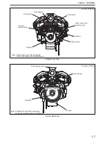
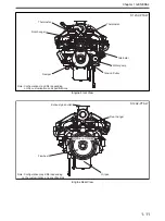
Страница 21: ...depending on the customization and specifications Water pump Damper Alternator Tension Pulley Thermostat Thermostat Front hanger S12A2 PTA Note Configuration may differ depending on the customization and specifications Direction of rotation Direction of rotation Flywheel Direction of rotation Oil pan Exhaust gas outlet Rear hanger ...

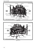
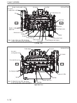
Страница 22: ...uel injection pump Rear Front Governor Water drain cock Fuel feed pump Oil level gauge Stop solenoid Fuel filter Cooling water inlet Cooling water outlet Turbocharger Stop lever Breather Governor oil filter S12A2 PTA Note Configuration may differ depending on the customization and specifications Oil filter Front Rear Fuel injection pump Fuel feed pump Oil cooler Fuel filter Water drain cock Bypass...

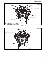
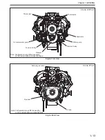
Страница 23: ...customization and specifications Water pump Damper Alternator Tension Pulley Thermostat Thermostat Front hanger S12A2 PTA2 Note Configuration may differ depending on the customization and specifications Direction of rotation Direction of rotation Flywheel Direction of rotation Oil pan Exhaust gas outlet Rear hanger ...

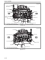
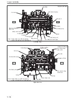
Страница 24: ...ter drain cock Fuel feed pump Oil level gauge Stop solenoid Fuel filter Cooling water inlet Silencer Turbocharger Stop lever Breather Actuator Fuel filter wire mesh type Rear Front Cooling water outlet S12A2 PTA2 Note Configuration may differ depending on the customization and specifications Oil filter Fuel injection pump Fuel feed pump Oil cooler Fuel filter Water drain cock Bypass oil filter Sta...

Страница 25: ...ration may differ depending on the customization and specifications Water pump Damper Alternator Thermostat Thermostat Front hanger S12A2 Y1PTA2 Note Configuration may differ depending on the customization and specifications Direction of rotation Direction of rotation Flywheel Direction of rotation Oil pan Exhaust gas outlet Rear hanger ...

Страница 26: ...Water drain cock Fuel feed pump Oil level gauge Stop solenoid Fuel filter Cooling water inlet Cooling water outlet Stop lever Breather Actuator Fan Fuel filter wire mesh type Rear Front S12A2 Y1PTA2 Note Configuration may differ depending on the customization and specifications Oil filter Fuel injection pump Fuel feed pump Oil cooler Fuel filter Water drain cock Bypass oil filter Starter Front Rea...

Страница 27: ...s Water pump Damper Alternator Tension Pulley Thermostat Thermostat Front hanger Air cooler cooling water outlet S12A2 PTK Note Configuration may differ depending on the customization and specifications Direction of rotation Direction of rotation Flywheel Direction of rotation Oil pan Exhaust gas outlet Rear hanger Air cooler cooling water inlet ...

Страница 28: ...et Fuel injection pump Water drain cock Fuel feed pump Oil level gauge Stop solenoid Fuel filter Engine cooling water inlet Engine cooling water outlet Turbocharger Stop lever Breather Actuator Rear Front S12A2 PTK Note Configuration may differ depending on the customization and specifications Oil filter Fuel injection pump Fuel feed pump Oil cooler Fuel filter Water drain cock Bypass oil filter S...

Страница 29: ... customization and specifications Water pump Damper Alternator Tension Pulley Thermostat Thermostat Front hanger S12A2 PTAW Note Configuration may differ depending on the customization and specifications Flywheel Oil pan Exhaust gas outlet Rear hanger Direction of rotation Direction of rotation Direction of rotation ...

Страница 30: ...vel gauge Stop solenoid Fuel filter Engine cooling water inlet Engine cooling water outlet Stop lever Breather Actuator Fan Fuel filter wire mesh type Air cooler cooling water outlet Rear Front S12A2 PTAW Note Configuration may differ depending on the customization and specifications Oil filter Fuel injection pump Fuel feed pump Oil cooler Fuel filter Water drain cock Bypass oil filter Starter Fro...

Страница 31: ... depending on the customization and specifications Water pump Damper Alternator Tension Pulley Thermostat Thermostat Tension Pulley S12A2 PTAW Note Configuration may differ depending on the customization and specifications Direction of rotation Direction of rotation Flywheel Direction of rotation Oil pan Exhaust gas outlet ...

Страница 32: ...level gauge Stop solenoid Fuel filter Stop lever Breather Actuator Fuel filter wire mesh type Rear Front Engine cooling water inlet S12A2 Y2PTAW Note Configuration may differ depending on the customization and specifications Oil filter Fuel injection pump Fuel feed pump Air cooler Fuel filter Water drain cock Bypass oil filter Starter Air cooler cooling water inlet Front Rear Air cooler cooling wa...

Страница 33: ...jection nozzle Fuel injection pump Fuel filter From fuel tank To fuel tank To right side of engine From right side of engine Turbocharger Camshaft Crankshaft Fuel Injection Pump Timing gear Piston cooling nozzle Piston Rocker shaft Woodward PSG type governor Main gallery Oil cooler Bypass oil filter Water pump Oil filter Oil strainer Safety valve Oil pump Governor Governor oil filter ...

Страница 34: ...r Piston cooling nozzle Piston Rocker shaft Main gallery Oil cooler Bypass oil filter Water pump Oil filter Oil strainer Safety valve Oil pump TOHO SEISAKUSHO SG4017 type actuator spec Woodward PROACT type governor spec Air cooler left Water outlet pipe Water jacket Air cooler right Oil cooler Thermostat Water bypass pipe Water pump Radiator PTA PTA2 spec Radiator cooling ...

Страница 35: ...t Air cooler cooling water inlet Air cooler cooling water outlet Engine cooling water outlet Engine cooling water outlet Thermostat Thermostat Oil cooler Air cooler water pump Water jacket Jacket water pump Air cooler cooling water outlet Air cooler cooling water inlet Engine cooling water outlet Engine cooling water outlet Engine cooling water inlet Y2PTAW spec Two way pump system external coolin...

Страница 36: ...et Air cooler right MTK MPTK spec with fresh water cooling system or seawater cooling system Oil cooler Thermostat Water bypass pipe Water pump Water pump Air cooler cooling water inlet Air cooler cooling water outlet Expansion tank Heat exchanger Exhaust gas outlet Air cooler From air cleaner Air cooler Turbocharger From air cleaner Turbocharger Exhaust Inlet Cylinder ...

Страница 37: ... of the rocker cover of No 1 cylinder and shows the following informa tion Valve clearance Firing order Fuel injection timing Connecting rod weight rank Caution Plate 3 3 Emissions Certification Label The emission certification label that shows compliance with emission requirements is attached to the engine 1 2 7 8 9 10 11 12 3 4 5 6 Front Rear Left Right Cylinder No 1 2 7 8 9 10 11 12 3 4 5 6 VAL...

Страница 38: ... 10 6 7 2 11 4 9 Direction of rotation Counterclockwise as viewed from flywheel side Engine oil Class CF or CH 4 API service classification Equipment name Specification name PTA PTA S PTA2 Y1PTA PTAW Y2PTAW 2 PTK MPTA MPTK C2MPTK MTK Camshaft Overlap 110 Right 32605 40101 Left 32605 40201 Y Y Y Y Y Y Y Y Y Y Y Cylinder liner 32507 62400 Y Y Y Y Y Y Y Y Y Y 32607 03400 Y Oil pan Shallow type 32613 ...

Страница 39: ...Y Y Fuel injection nozzle Screw adjust type 32561 76050 Y Y Y Screw adjust type 32561 64010 Y Y Y Y Screw adjust type 32561 79010 Y Y Screw adjust type 32561 54010 Y Y Shim adjust type 35A61 11030 Y Y Y Y Shim adjust type 32661 11070 Y Y Shim adjust type 32661 11060 Y Shim adjust type 32661 01050 Y Y Shim adjust type 32661 01090 Y Fuel filter Diesel oil 32562 61010 Y Y Y Y Y Y Diesel oil 32562 600...

Страница 40: ...Y Y TD10L2 45VRC 34 Y Y Y TD10L2 45VRC 28 Y TD10L2 45VRC 34 PTA2 Y TD10L2 48VRC 34 PTA2 Y Air cooler Fresh water cooling Right 32630 46021 Left 32630 45021 Y Y Y Y Y Y Y External cooling Right 32630 11021 Left 32630 12021 Y PTA2 Right 32630 37020 Left 32630 37030 Y Y Sea water cooling 32655 00021 Y Y Fan D1250 PUSH 46648 03400 Y Y Y Y Y Y Y Heat exchanger Expansion tank 45146 98200 Y Heat exchange...

Страница 41: ...ERAL Alternator 30A 04343 38000 Y Y Y 30A 34468 21100 Y Y Y Y 24A 04344 05001 Y Y 35A 04343 35500 Y Y Y Y Y 50A 34368 02400 Y Equipment name Specification name PTA PTA S PTA2 Y1PTA PTAW Y2PTAW 2 PTK MPTA MPTK C2MPTK MTK ...

Страница 42: ......

Страница 43: ...Tightening Torque Table 2 21 2 1 Tightening Torque Spec for Basic Engine 2 21 2 2 Tightening Torque Spec for Fuel System 2 22 2 3 Tightening Torque Spec for Lubrication System 2 22 2 4 Tightening Torque Spec for Cooling System 2 22 2 5 Tightening Torque Spec for Inlet and Exhaust System 2 22 2 6 Tightening Torque Spec for Electrical System 2 23 2 7 Tightening Torque Spec for Air Start System 2 23 ...

Страница 44: ......

Страница 45: ...cm2 4267 psi 0 29 Mpa 300 kgf cm2 4267 psi At oil temperature range from 90 to 100 C 194 to 212 F When idling 0 20 to 0 29 MPa 300 kgf cm2 4267 psi 0 15 Mpa 300 kgf cm2 4267 psi Valve timing Inlet Open BTDC 55 At normal valve clearance 0 mm Close ABDC 65 Exhaust Open BBDC 65 Close ATDC 55 Inlet Open BTDC 11 2 crank angle Valve clearance 2 mm 0 08 in Close ABDC 21 Exhaust Open BBDC 21 Close BTDC 11...

Страница 46: ... 1 85 0 0728 1 75 to 1 95 0 0689 to 0 0768 2 3 0 0906 Valve margin Inlet 2 9 0 114 2 7 to 3 1 0 1063 to 0 1220 2 0 0 098 after refacing Exhaust 3 0 0 118 2 8 to 3 2 0 1102 to 0 1260 Inside diameter of valve seat counterbore Inlet 58 000 to 58 030 2 2835 to 2 2846 58 09 2 2870 Exhaust 54 000 to 54 030 2 1260 to 2 1272 54 09 2 1295 Outside of valve seat Inlet Standard 58 100 to 58 130 2 2874 to 2 28...

Страница 47: ...n at 95 8 mm 3 77 in with right angles to the piston pin In one engine Weight dif ference P N 32517 91101 91101 stamp 32617 00701 00701 stamp Within 15 g 0 53 oz P N 32517 91201 91201 stamp 32617 00600 00600 stamp Within 20 g 0 71 oz Piston pin bore inside diameter ø58 2 28 58 002 to 58 012 2 2835 to 2 2839 58 040 2 2850 Protrusion 0 229 to 0 839 0 0090 to 0 0330 Cylinder head gasket Thickness whe...

Страница 48: ...0197 or less Rear mecha nism Backlash between crank gear and idler gear 0 11 to 0 25 0 0043 to 0 0098 0 50 0 0197 Backlash between fuel injection pump gear and camshaft gear 0 12 to 0 18 0 0047 to 0 0071 0 50 0 0197 Backlash between idler gear and fuel injection pump gear 0 12 to 0 18 0 0047 to 0 0071 0 50 0 0197 Backlash between oil pump gear and crankshaft gear 0 12 to 0 18 0 0047 to 0 0071 0 50...

Страница 49: ...h 0 03 0 0012 Circularity of journal and crankpin Diameter difference 0 01 0 0004 or less 0 03 0 0012 Cylindricity of journal and crankpin Diameter difference 0 01 0 0004 or less 0 03 0 0012 Fillet radius of pin R7 0 28 6 8 to 7 0 0 2677 to 0 2756 Fillet radius of journals R7 0 28 6 8 to 7 0 0 2677 to 0 2756 Hardness of journals and crankpins Hv 620 Finishing surface roughness Ra 0 2 μm 0 008 µin ...

Страница 50: ...02 to 0 1929 4 76 0 1874 Over size 0 25 0 0098 5 25 0 2067 5 08 to 5 15 0 2000 to 0 2028 5 01 0 1972 0 50 0 0197 5 50 0 2165 5 33 to 5 40 0 2098 to 0 2126 5 26 0 2071 0 75 0 0295 5 75 0 2264 5 58 to 5 65 0 2197 to 0 2224 5 51 0 2169 Crankcase Distortion of top surface 0 1 0 004 or less 0 20 0 0079 Inside diameter of main bearing bore ø137 5 4 137 000 to 137 025 5 3937 to 5 3947 137 045 5 3955 Dept...

Страница 51: ...61 11030 J mark 29 4 MPa 300 kgf cm 4267 psi 29 9 to 30 7 MPa 304 to 313 kgf cm 4324 to 4452 psi Orifice cone angle P N 32561 57090 E mark 32561 79010 B mark 155 P N 32561 54010 C mark 32561 64010 A mark 157 P N 32561 76050 mark 32661 01050 P mark 32661 01090 N mark 32661 11060 2M mark 32661 11070 J mark 32A61 11030 J mark 158 Orifice diame ter P N 32661 01050 P mark 0 23 0 0091 P N 32561 57090 E ...

Страница 52: ...ft bearing fit ø35 1 38 35 002 to 35 013 1 3780 to 1 3785 ø40 1 57 40 002 to 40 013 1 5749 to 1 5753 S7S spec Drive case P N 32625 09100 Inside diameter of case bearing housing ø80 3 15 79 988 to 80 018 3 1491 to 3 1503 ø100 3 94 99 987 to 100 022 3 9365 to 3 9379 Injection pump drive shaft bearing Out side diame ter Small ø80 3 15 79 987 to 80 000 3 1491 to 3 1496 Large ø100 3 94 99 985 to 100 00...

Страница 53: ...arge ø90 3 54 89 985 to 90 000 3 5427 to 3 5433 Inside diame ter Small ø20 0 79 19 990 to 20 000 0 7870 to 0 7874 Middle ø40 1 57 39 988 to 40 000 1 5743 to 1 5748 Large ø40 1 57 39 988 to 40 000 1 5743 to 1 5748 Drive case cover bearing Out side diame ter Small ø47 1 85 46 890 to 47 000 1 8461 to 1 8504 Middle ø62 2 44 61 987 to 62 000 2 4404 to 2 4409 Large ø72 2 83 71 987 to 72 000 2 8341 to 2 ...

Страница 54: ...o 20 000 0 7870 to 0 7874 Middle ø40 1 57 39 988 to 40 000 1 5743 to 1 5748 Large ø45 1 77 44 988 to 45 000 1 7712 to 1 7717 Drive Case Cover bearing Out side diame ter Small ø47 1 85 46 890 to 47 000 1 8461 to 1 8504 Middle ø62 2 44 61 987 to 62 000 2 4404 to 2 4409 Large ø80 3 15 79 987 to 80 000 3 1491 to 3 1496 Inside diame ter Small ø20 0 79 19 990 to 20 000 0 7870 to 0 7874 Middle ø30 1 18 2...

Страница 55: ...0 130 to 0 300 0 0051 to 0 0118 0 350 0 0138 Drive shaft outside diameter ø34 1 34 33 944 to 33 960 1 3364 to 1 3370 33 920 1 3354 Driven shaft outside diameter 33 944 to 33 960 1 3364 to 1 3370 33 920 1 3354 Bushing inside diameter 34 000 to 34 025 1 3386 to 1 3396 34 055 1 3407 Safety valve opening pressure 1 42 MPa 14 5 kgf cm 206 psi Safety valve spring installed length load 97 833 6 N 85 kgf ...

Страница 56: ...Outside diameter of bracket bearing fit ø20 0 79 19 987 to 20 000 0 7869 to 0 7874 P N 32645 18401 Inside diameter of pulley bearing fit ø90 3 54 89 972 to 89 994 3 5422 to 3 5431 Bearing Outside diameter ø90 3 54 89 985 to 90 000 3 5427 to 3 5433 Inside diameter ø40 1 57 39 988 to 40 000 1 5743 to 1 5748 Bracket bearing Outside diameter to fit ø40 1 57 39 984 to 40 000 1 5742 to 1 5748 Fan Inside...

Страница 57: ... 04 Inside diameter of bearing fit Pump case ø62 2 44 61 988 to 62 018 2 4405 to 2 4416 Bearing cover ø68 2 6 67 961 to 67 991 2 6756 to 2 6768 Bearing Outside diameter ø68 2 6 67 987 to 68 000 2 6766 to 2 6772 Inside diameter ø28 1 10 27 990 to 28 000 1 1020 to 1 1024 Outside diameter of shaft fit to bearing ø28 1 10 28 002 to 28 015 1 1024 to 1 1030 Impeller front clearance 0 8 0 032 0 5 to 1 1 ...

Страница 58: ...ring ø50 1 97 50 002 to 50 013 1 9686 to 1 9690 ø45 1 77 45 002 to 45 013 1 7717 to 1 7722 V belt Inside diameter of case bearing housing ø100 3 94 99 987 to 100 022 3 9365 to 3 9379 ø110 4 33 109 987 to 110 022 4 3302 to 4 3316 Bearing Large Outside diameter ø110 4 33 109 985 to 110 000 4 3301 to 4 3307 Inside diameter ø40 1 57 39 988 to 40 000 1 5743 to 1 5748 Small Outside diameter ø100 3 94 99...

Страница 59: ...0 2 to 0 8 0 0079 to 0 0315 Adjust with the adjust washer Clearance between pinion shaft and bearing 0 25 0 0098 Brush length 22 to 23 0 87 to 0 91 13 0 51 Brush spring load 44 1 N 4 5 kgf 9 9 lbf 40 2 N 4 1 kgf 9 0 lbf With brush installed Armature Front shaft outside diameter ø20 0 79 20 002 to 20 011 0 7875 to 0 7878 Front bearing fit diameter ø47 1 85 47 1 1 854 Front shaft bearing Outside dia...

Страница 60: ...h less Output cur rent at 27 V Rotating speed min 1 2500 30 A or more when cold 5000 35 A or more when engine is hot Regulator adjusting voltage Alternator 5000 min 1 load 5A or less 28 5 0 5 V Field coil resistance 20 C 68 F 7 3 to 8 5 Ω P N 04343 38000 Self excit ing type with brush Output cur rent at 27 V Rotating speed min 1 2500 26 A or more when engine is hot 5000 30 A or more when engine is...

Страница 61: ...s 28 5 0 5 V P N 34468 21100 Initial exciting type with brush Output cur rent at 27 V Rotating speed min 1 1500 13 A or higher when engine is hot 2500 22 A or higher when engine is hot 5000 30 A or more when engine is hot Regulator adjusting voltage Alternator 5000 min 1 load 5A or less 28 5 0 5 V Belt tension cogged type 10 to 15 0 39 to 0 59 When the cen ter of the belt is pushed with a force of...

Страница 62: ... 47 34 3 47 7 64 26 2 65 5 85 21 2 14 4 72 17 1 73 3 82 4 62 6 32 13 94 41 4 18 9 22 31 3 16 6 97 25 2 55 5 62 21 2 14 4 72 5 72 7 34 16 19 48 4 89 10 79 36 3 67 8 09 29 2 96 6 52 24 2 45 5 40 6 82 8 36 18 43 55 5 61 12 36 41 4 18 9 22 33 3 37 7 42 27 2 75 6 07 7 93 9 48 20 91 62 6 32 13 94 46 4 69 10 34 37 3 77 8 32 31 3 16 6 97 8 103 10 50 23 16 69 7 04 15 51 51 5 20 11 47 41 4 18 9 22 34 3 47 7...

Страница 63: ... 1 5 Rocker shaft bracket 12 x 1 75 49 2 5 5 0 25 36 1 81 Rocker arm lock nut 12 x 1 25 64 6 4 6 5 0 65 47 4 70 Bridge lock nut 10 x 1 25 55 5 5 5 6 0 56 40 5 4 05 Camshaft gear 30 x 1 5 294 15 30 1 5 217 10 9 Left hand thread Main bearing cap 24 3 0 588 29 60 3 0 434 22 Wet Note b Main bearing cap side bolt 16 2 0 147 7 4 15 0 75 109 5 42 Wet Note b Piston cooling nozzle 12 x 1 75 34 1 7 3 5 0 17...

Страница 64: ...tening method Fuel filter air vent plug 8 x 1 25 9 1 0 9 0 1 6 5 0 7 Nozzle tip retaining nut 19 1 0 68 5 9 5 7 1 51 7 Nozzle inlet connector 14 1 5 74 5 7 5 0 5 54 3 3 6 Nozzle holder cap nut 14 x 1 0 44 5 4 5 0 5 32 6 3 6 Nozzle holder eye bolt 10 1 0 17 5 2 5 1 75 0 25 12 66 1 81 Nozzle gland nut 12 x 1 25 59 2 9 6 0 3 43 2 2 S7S feed pump inlet 14 1 5 27 2 2 75 2 5 19 89 18 1 Description Dia x...

Страница 65: ... Pulley nut 20 x 1 5 147 15 14 99 1 53 108 42 11 07 Retainer tightening screw 5 0 8 3 9 1 0 4 0 1 2 9 0 7 Through bolt 6 x 1 0 5 4 1 5 0 55 0 15 3 98 1 08 Regulator assembly tightening screw 5 0 8 3 9 1 0 4 0 1 2 9 0 7 Rectifier assembly tightening screw 5 0 8 3 9 1 0 4 0 1 2 9 0 7 B terminal nut 5 0 8 6 9 0 9 0 7 0 09 5 1 0 65 E terminal nut 5 0 8 6 9 0 9 0 7 0 09 5 1 0 65 Coil assembly tightenin...

Страница 66: ...3 4 24 6 60 6 1 44 1 12 x 1 25 17 0 67 60 6 1 44 1 108 11 0 79 6 14 1 5 22 0 87 97 9 9 71 6 176 17 9 129 5 16 x 1 5 24 0 94 145 14 8 107 1 262 26 7 193 1 18 x 1 5 27 1 06 210 21 4 154 8 378 38 5 278 5 20 x 1 5 30 1 18 291 29 7 214 8 524 53 4 386 2 22 x 1 5 32 1 26 385 39 3 284 3 694 70 8 512 1 24 1 5 36 1 42 487 49 7 359 5 878 89 5 647 4 27 1 5 41 1 61 738 75 3 544 7 1328 135 5 980 1 Metric course...

Страница 67: ...8 3 68 20 1 5 27 1 06 98 10 10 0 1 0 72 28 7 37 24 1 5 32 1 26 147 15 15 0 1 5 108 42 11 06 27 1 5 41 1 61 226 20 23 0 2 0 166 69 14 75 Dry Nominal Cap nut thread size Dia Pitch M thread Width across flats mm in N m kgf m lbf ft 63 14 1 5 19 0 75 39 4 28 76 80 16 1 5 22 0 87 49 5 36 14 100 20 1 5 27 1 06 78 8 57 53 120 22 1 5 30 1 18 98 10 72 28 150 27 1 5 32 1 26 157 16 115 80 180 30 1 5 36 1 42 ...

Страница 68: ......

Страница 69: ...3 1 Chapter 3 SERVICE TOOLS 1 Special Tools 3 3 ...

Страница 70: ......

Страница 71: ...26 1 42 in Idler bushing puller 32591 02500 Idler Bushing Replace Bushing inside diam ø50 X 55 mm 1 97 X 2 17 in Eye bolt 45815 32201 Piston lift Eye bolt 45815 32301 Piston lift Eye bolt 05930 00200 Gear case lift Eye nut 08014 00003 Cylinder head assembly install remove Front seal installer assembly 32691 00042 Front oil seal install Rear seal installer assembly 32591 07012 Rear oil seal install...

Страница 72: ...l Install Guide height 27 5 mm 1 08 in Stem seal height 30 3 mm 1 19 in Socket 32591 02800 Camshaft connector installation removal Adapter 32591 04300 Main bearing cap Remove Ring expander 37191 03200 Piston ring install remove Applicable diam o101 6 to 177 8 mm 4 00 to 7 00 in Cylinder liner remover 32591 14100 Cylinder Liner Remove Applicable cylinder liner inner diam ø150 mm 5 91 in Installer 3...

Страница 73: ... ø40 mm 1 57 in 30091 08800 Valve lapping Valve seat cutter Shaft 37591 06400 Valve Seat Reface Width across flats 32 mm 1 26 in Applicable seat inside outside diame ter ø45 to 66 1 77 to 2 60 in Cutter 37591 06430 Socket wrench 32591 01100 Cylinder head bolt Install and Remove Inlet valve seat caulking tool 35A91 05010 Inlet valve seat installation Exhaust valve seat caulking tool 35A91 05020 Exh...

Страница 74: ...00 0 6 mm 0 024 in 32691 01600 Connecting rod Assembly Fuel system Nozzle tester 04239 00050 Fuel injection nozzle opening pressure measure Lubrication system Oil pump bush Puller 32691 02700 Oil Pump Bushing Replace Bushing inside outside diam ø34 37 mm 1 34 1 46 in Cooling system Oil seal installer 32591 03200 Water pump oil seal Press in Thread cover 37191 06600 Water pump Shaft Press in Bearin...

Страница 75: ...91 04200 Fan drive bearing Press in Bearing installer 32691 04300 Fan drive bearing Press in Fan pulley adapter 32691 07100 Fan Pulley Lock Air start system Starter valve adapter 32591 01200 Starter Valve Remove Inspection and measurement Compression gauge 33A91 01700 Compression Pressure Measure Measurement range 0 to 7 MPa 0 to 71 kgf cm2 0 to 1015 psi Gauge adapter 36291 02200 Compression Press...

Страница 76: ...3 8 Chapter 3 SERVICE TOOLS Inspection and measurement Belt gauge 32591 09100 Belt tension measure Maintenance item Tool name Part No Illustration Usage 30 25 20 15 10 5 2 1 ...

Страница 77: ...4 1 Chapter 4 OVERHAUL INSTRUCTIONS 1 Determining Overhaul Timing 4 3 2 Compression Pressure Measure 4 4 ...

Страница 78: ......

Страница 79: ...ecrease 2 Fuel consumption increase 3 Engine oil consumption increase 4 Combustion gas leak increase by cylinder liner and piston ring wear and as a result blow by gas increase through the breather Visually check the blow by amount 5 Gas leak increase due to poor seating of inlet and exhaust valves 6 Difficult starting 7 Noise increase from engine parts 8 Abnormal exhaust color after engine warm u...

Страница 80: ... measured because of a low crank ing speed 4 If the measured value exceeds the limit overhaul the engine Compression Pressure Measure a Be sure to measure the compression pressure of all cylinders It is not a clever way to measure the compression pressure of only two or three cylinders and assume the compression pres sure of all other cylinders Cylinders are all inde pendent b Also be sure to chec...

Страница 81: ...ernor Drive and Fuel Injection Pump Accessory Drive Remove 5 11 2 10 Camshaft Gear Remove 5 12 2 11 Camshaft Remove 5 12 2 12 Idler Shaft Remove 5 12 2 13 Rear Plate Remove 5 13 3 Front Mechanism Disassemble and Inspect 5 14 3 1 Fan Fan Bracket Assembly and Belt Remove 5 15 3 2 Damper Face and Radial Runout Measure 5 15 3 3 Front Pulley Damper and Crankshaft Pulley Remove 5 15 3 4 Front Cover Remo...

Страница 82: ......

Страница 83: ... 18 2 3 4 5 6 7 24 Replace Replace Replace Replace Replace Replace Replace Wear Wear Corrosion Wear at both ends bend Wear oil hole clogging Stem face portion wear corrosion flaw carbon deposit Cam contact face and outer peripheral contact face wear Crack flaw settling rubber portion crack Crack carbon deposit flaw scale deposit Contact wear Flaw Wear oil hole clogging Settling crack Crack oil lea...

Страница 84: ...Inspect Inspect the valve clearance and know the current condition For the inspection procedure refer to Valve Clearance Inspect and Adjust of ASSEMBLY OF BASIC ENGINE Valve Clearance Inspect Sealing washers Eye bolt Clamp Fuel injection pipe Fuel leak off pipe When removing the nozzle assembly with nozzle remover be careful not to get caught your fingers between the nozzle remover weight bar and ...

Страница 85: ...ft Assembly Disassemble 1 6 Clearance Between Bottom Face of Valve Bridge and Top Face of Valve Rotator Inspect Inspect the clearance between the bottom face of valve bridge and the top face of valve rotator and know the cur rent condition For the inspection procedure refer to Clearance Between Bottom Face of Valve Bridge and Top Face of Valve Rota tor Measure of ASSEMBLY OF BASIC ENGINE Clearance...

Страница 86: ...in the cylinder head in a po sition Therefore pull the cylinder head vertical to the mounting surface to remove 3 Remove the cylinder head gasket Cylinder Head Assembly Remove 1 9 Valve Sinkage Measure Measure the valve sinkage and know the current condition For the measurement procedure refer to Valve Sinkage Measure of ASSEMBLY OF BASIC ENGINE Bridge cap Screw When removing the cylinder head gas...

Страница 87: ...e Guide Remove Do not remove the nozzle gland stud bolt and the bridge guide from the cylinder head unless they are defective If they are removed see Nozzle Gland Stud Bolt and Bridge Guide Inspect and Replace of INSPECTION AND REPAIR OF BASIC ENGINE Nozzle Gland Stud Bolt and Bridge Guide Remove 1 12 Fuel Connector Remove Do not remove the fuel injection connector fuel leak off connector from the...

Страница 88: ...wel hole defect Crack dowel hole defect flaw on gear abnormal wear Flaw wear key groove defect Wear flaw deterioration Electronic governor spec Oil pressure governor spec Hour meter spec Tachometer spec Non attachment spec Non attachment spec Non attachment spec Non attachment spec Wear flaw deterioration 13 14 11 12 5 3 8 9 9 9 10 2 1 1 4 6 7 Disassembling Sequence 1 Pick up electronic governor s...

Страница 89: ...revent it from falling 2 Lift the timing gear case to disengage the dowel pins and remove the timing gear case 3 Remove the oil seal from the timing gear case Note Do not reuse the removed oil seal Timing Gear Case Remove Face runout measuring plane Radial runout measuring plane a Be careful not to drop or bump the flywheel It can not only cause damage to parts but also lead to personnel injury b ...

Страница 90: ... play and know the current con dition For the measurement procedure refer to Idler Gear End Play Measure of ASSEMBLY OF BASIC ENGINE Idler Gear End Play Measure 2 6 Camshaft End Play Measure Measure the camshaft end play and know the current condi tion For the measurement procedure refer to Camshaft End Play Measure of ASSEMBLY OF BASIC ENGINE Camshaft End Play Measure Camshaft gear Camshaft gear ...

Страница 91: ...p Gear Remove 2 9 Governor Drive and Fuel Injection Pump Accessory Drive Remove Remove the governor drive oil pressure governor spec and fuel injection pump accessory drive from the rear plate Refer to the chapter FUEL SYSTEM for disassembly inspection and assembly Governor Drive and Fuel Injection Pump and Accessory Drive Remove The camshaft gear mounting nuts are left hand threaded Be sure to tu...

Страница 92: ... to the top of the crankcase and remove the camshaft to the rear of the engine Camshaft Remove 1 Camshaft Remove 2 2 12 Idler Shaft Remove Screw two jack bolts evenly into the jack bolt holes and remove the idler shaft Idler Shaft Remove Camshaft gear Puller Threaded holes M10 1 25 mm Remove the camshaft by lifting from Crankcase top face paying attention not to damage the Crankcase and camshaft C...

Страница 93: ...5 13 Chapter 5 DISASSEMBLY OF BASIC ENGINE 2 13 Rear Plate Remove Remove the rear plate from the crankcase Rear Plate Remove Dowel pin ...

Страница 94: ...ffer in accordance with the customization and specification Belt groove wear With pulley V belt With pulley ribbed belt Fan attachment spec Oil pipe With cranking pulley Crack dowel hole defect Crack oil leak Replace Slinger portion Seal lip portion Double installation spec Front oil seal assembly in the form of a cassette combing an seal lip and slinger Front oil seal should be replaced whenever ...

Страница 95: ...he groove of front pulley to support Screw two jack bolts evenly into the jack bolt holes and remove the pulley Front Pulley Remove 3 While supporting the damper with a sling screw two jack bolts evenly into the jack bolt holes and remove the damper Damper Remove 4 Screw two jack bolts evenly into the jack bolt holes and remove the crankshaft pulley from the crankshaft Crankshaft Pulley Remove Fac...

Страница 96: ...l seal seal lip portion from the front cover 3 Remove the oil seal slinger portion from the crank shaft by tapping lightly or prying it Front Cover Remove When removing the oil seal slinger portion be careful not to damage the crankshaft If the crankshaft has a flaw oil will leak from its flaw even if new oil seal is installed Jack bolt M10 1 5 mm Front cover Oil seal Bolt Pointer ...

Страница 97: ...otrusion Measure Cylinder Liner Piston and Connecting Rod Disassemble and Inspect 12 11 10 9 8 7 6 5 4 3 2 1 Crack oil hole clogging Outer peripheral surface scratch crack flaw carbon deposit Inner face wear flaw discoloration Inner and outer peripheral surface flaw seizure peeling Replace Deformation wear Wear flaw Flaw Serrated portion wear crack Inner face scratches wear outer peripheral O ring...

Страница 98: ...nner surface of the cyl inder liner Hard Carbon Deposits on the Upper Part of Cylinder Liner Remove 4 4 Connecting Rod Cap Remove Using a socket wrench remove the connecting rod bolts through the inspection window on the side of the crankcase and remove the connecting rod cap and connecting rod bear ings Note a Be careful not to damage the connecting rod bear ings by dropping them into the oil pan...

Страница 99: ...ul as you may suffer hand injuries from accidental movement of the connecting rod a When pulling out the piston be careful not to drop the upper connecting rod bearing b When removing piston be careful not to damage cylinder liner by connecting rod runout c When only a few pistons remain in the cylinders the crankshaft tends to turn by weight imbalance Be sure to hold the crankshaft to prevent it ...

Страница 100: ...ting rod and piston while adjusting the supporting position When the oil ring is slid out of the cylinder liner care fully put the piston on the top face of cylinder liner 6 Lift the piston with eye bolt on the piston top and pull out the piston from cylinder liner Crankshaft Rotate 1 Crankshaft Rotate 2 Connecting Rod Big End Push Up 4 6 Piston Ring Remove Hold the piston and connecting rod in a ...

Страница 101: ...E Cylinder Liner Inside Diameter Measure 4 9 Cylinder Liner Flange Protrusion Measure Measure the cylinder liner flange protrusion and know the current condition For the measurement procedure refer to Cylinder Liner Flange Protrusion Measure of ASSEMBLY OF BASIC ENGINE Cylinder Liner Flange Protrusion Measure 4 10 Cylinder Liner Remove 1 Set the cylinder liner remover to the cylinder liner Note Us...

Страница 102: ...11 10 8 7 6 5 4 3 2 1 9 Scale deposit flaw crack oil hole clogging Inner and outer peripheral face flaw corrosion flaking Wear flaw crack Inner and outer peripheral face flaw corrosion flaking Flaw Peeling wear contact Wear Valve operation oil hole clogging Local contact crack on counterbore fretting corrosion on fitting bore of cylinder liner Crack Wear Replace Flaw Oil jet pipe bend deformation ...

Страница 103: ... 5 3 Piston Cooling Nozzle Remove Remove the piston cooling nozzle from the crankcase 5 4 Main Bearing Cap Remove 1 Remove the main bearing cap bolts and side bolts 2 Install the adapter to main bearing cap Install the nozzle remover to adapter 3 Remove the main bearing cap from the crankcase 4 Remove the lower main bearing from the main bearing cap 5 Remove the lower thrust plate from the rearmos...

Страница 104: ... Place cloth belts or pads in the positions before lifting crankshaft 3 Remove the upper main bearing from crankcase pay ing attention to the lug position and remove the upper thrust plate on the rear side Crankshaft Remove a Before removing the crankshaft remove the front side upper thrust plate first and be careful not to drop it into crankcase b When placing the crankshaft onto a pallet or othe...

Страница 105: ...ler Bushing Replace 6 11 2 3 Cam Lift of Cam Shaft Lobe Measure 6 11 2 4 Camshaft Runout Measure 6 12 2 5 Camshaft Journal Outside Diameter Measure 6 12 2 6 Camshaft Bushing Inspect 6 12 2 7 Camshaft Bushing Replace 6 13 3 Front Mechanism Inspect and Repair 6 14 3 1 Damper Inspect Visually 6 14 3 2 Pulley Inspect 6 14 4 Piston and Connecting Rod Inspect and Repair 6 15 4 1 Piston Inspect Visually ...

Страница 106: ... Repair 6 24 5 5 Crankpin and Journal Outside Diameters Measure 6 24 5 6 Width of Crankpin and Rearmost Crank Main Journal Measure 6 26 5 7 Crankshaft Runout Measure 6 27 5 8 Crankshaft Gear Inspect 6 28 5 9 Crankshaft Gear Replace 6 28 5 10 Oil Seal Slinger Inspect 6 29 5 11 Oil Seal Slinger Replace 6 29 5 12 Main Bearing Inspect 6 30 5 13 Thickness of Main Bearing Shell Measure 6 30 5 14 Thrust ...

Страница 107: ...Measure the inside diameter of rocker bushing that has bee installed If the value is smaller than the standard ream the inside diameter to the standard Rocker Bushing Insert Rocker Bushing Position Item Nominal value Standard value Limit value Rocker bushing inside diameter ø32 mm 1 26 in 32 055 to 32 080 mm 1 26 to 1 26 in 32 100 mm 1 50 in Rocker shaft outside diameter ø32 mm 1 26 in 31 975 to 3...

Страница 108: ...alve guide remover Valve Guide Remove 2 With guide and seal installer press in the new valve guide slowly Valve Guide Press In Item Nominal value Standard value Limit value Valve stem outside diam eter Inlet ø10 mm 0 39 in 9 940 to 9 960 mm 0 0010 to 0 0044 in 9 910 mm 0 3902 in Exhaust ø10 mm 0 39 in 9 910 to 9 930 mm 0 3902 to 0 3909 in 9 880 mm 0 3890 in Valve guide inside diam eter ø10 mm 0 39...

Страница 109: ...ce coat ed with lead free coloring paste against valve seat Seat Width Inspect Contact condition between valve seat and valve 1 6 Valve Face Reface When the valve is re used by refacing use valve refacer Note a Grind the valve face with valve refacer adjusted to the specified angle b The valve margin is to be within the specified lim it If the dimensions after refacing does not meet the specified ...

Страница 110: ...eat with a new one Valve Seat Reface 1 8 Valve Seat Replace Be careful not to damage the machined surface of cylinder head when removing the valve seat 1 8 1 Valve Seat Remove With Valve Seat Puller Remove the valve seat with valve seat puller Valve Seat Remove With Valve Seat Puller 1 8 2 Valve Seat Remove by Welding To remove the valve seat weld a stud to valve seat as shown Then insert a shaft ...

Страница 111: ...mit value Remarks Inlet Inside diameter of valve seat counterbore 58 000 to 58 030 mm 2 2835 to 2 2846 in 58 09 mm 2 2870 in Valve seat outside diame ter Standard 58 100 to 58 130 mm 2 2874 to 2 2886 in Single red line 0 03 mm 0 0012 in 58 130 to 58 160 mm 2 2886 to 2 2898 in Double red lines 0 06 mm 0 0024 in 58 160 to 58 190 mm 2 2898 to 2 2909 in Triple red lines Exhaust Inside diameter of valv...

Страница 112: ...thin lead free coloring paste on the valve face and tap the valve face against the valve seat using a valve lapper to check for contact condition Compound Apply Valve and Valve Seat Lap 1 10 Valve Bridge Bridge Cap Valve Cotter and Valve Rotator Inspect 1 Inspect the contact surfaces between valve bridge and valve stem and the sliding surface between valve bridge and bridge guide If significant we...

Страница 113: ...t the nozzle gland stud bolt for bending or damage at threaded portion Inspect the bridge guide for uneven wear and damage on the sliding surface 1 14 1 Nozzle Gland Stud Install Tighten the nozzle gland stud bolt until it comes to the bot tom end 1 14 2 Bridge Guide Install Press in the bridge guide to the specified dimension Nozzle Gland Stud Bolt and Bridge Guide Install Nominal value Standard ...

Страница 114: ...ater Director Inspect and Replace 1 Inspect the water director and if corrosion or damage is found replace the water director with a new one 2 Orient the pipe and the opening of the water director as shown in the illustration and tap the water director lightly Water director mounting direction Refacing depth of cylinder head is to be mini mum Excessive grinding of the cylinder head may result in d...

Страница 115: ...cified dimension shown Note Reaming after press fit is necessary as the idler bush ings are supplied in a semi finished condition Idler Bushing Replace 2 3 Cam Lift of Cam Shaft Lobe Measure Measure the major diameter and minor diameter of cam lobe to know the cam lift If the value exceeds the limit replace the camshaft with a new one Cam Lift of Cam Shaft Lobe Measure Item Nominal value Standard ...

Страница 116: ...easure the camshaft bushing inside diameter with bushing installed in the crankcase If the value exceeds the limit replace the camshaft bushing with a new one Note Be careful not to damage the inner surface of camshaft bushing when measuring the inside diameter Camshaft Bushing Inside Diameter Measure Item Standard value Limit value Remarks Camshaft runout 0 05 mm 0 0020 in or less 0 08 mm 0 0031 ...

Страница 117: ...the oil hole and set bolt hole 3 Before securing the set bolt be sure to check that the set bolt is in alignment with the oil hole Camshaft Bushing Install Before tightening the set bolt be sure to check that the set bolt is in alignment with the set bolt hole in the camshaft bushing Make sure that the oil hole in the camshaft bushing is in alignment with the oil hole from the oil gallery Set bolt...

Страница 118: ... and discoloration and separation of coating due to overheating If any defect is found replace the damper with a new one Damper Inspect Visually 3 2 Pulley Inspect Check the belt groove of pulley for wear 1 Check the sinkage of belt 2 Fit a new belt tightly in pulley groove 3 If the belt sinks 1 6 mm 0 063 in or more below pul ley rim replace the pulley with a new one Pulley Wear Inspect 1 6 mm 0 ...

Страница 119: ... Groove Inspect 1 Remove all deposits such as carbon from each ring groove 2 Visually check each ring groove for wear or damage If faulty replace the piston with a new one Inspect the ring insert of No 1 compression ring groove by dye penetration test for cracks and separation Piston Ring Groove Inspect Item Part No ID stamp Com pres sion ratio Standard value Piston weight differ ence 32517 91101 ...

Страница 120: ...der liner Piston Ring End Gap Measure 4 8 Piston Pin Outside Diameter Measure Measure the piston pin outside diameter If the value exceeds the limit replace the piston pin with a new one Piston Pin Outside Diameter Measure Item Nominal value Standard value Limit value Piston pin bore inside diameter ø58 mm 2 28 in 58 002 to 58 012 mm 2 2835 to 2 2839 in 58 040 mm 2 2850 in Measurement direction Me...

Страница 121: ...ng Installer Use 1 3 With the connecting rod bearing removed from the con necting rod install the connecting rod cap to plate 4 Align the match mark and install the connecting rod to plate 5 Tighten the connecting rod bolts to the specified torque 6 Fix the connecting rod in place with bracket Connecting Rod Bushing Installer Use 2 Item Nominal value Standard value Limit value Inside diameter of c...

Страница 122: ...nsert the assem bly into the connecting rod bushing while aligning the match mark red scribed line on the collar A with that on the adapter 3 With pressing machine apply pressure slowly on man drel head to push out the connecting rod bushing Connecting Rod Bushing Installer Use 3 Mark on collar A red stamp mark Mark on adapter red stamp mark Mandrel Collar A Adapter Base Connecting rod bushing ...

Страница 123: ...e of connecting rod bushing and oil hole of connecting rod Press in the bushing into connecting rod with pressing machine Connecting Rod Bushing Installer Use 6 a Make sure that the match marks red lines on col lars A and B are align b Make sure that the oil hole of connecting rod bushing is in alignment with match mark red ø4 mm 0 16 in on collar A Connecting rod bushing oil hole Collar A match m...

Страница 124: ...d by subtracting the minimum value from the maximum value among measure ments of A B and C If the value exceeds the limit replace the connecting rod with a new one Connecting Rod Big End Bore Diameter Measure Item Standard value Inside diameter of connecting rod bush ing 58 020 to 58 040 mm 2 2843 to 2 2850 in Inside diameter of connecting rod bushing Bushing inner surface roughness Ra0 4μm _ ٖ ٖ ...

Страница 125: ...nd Bolt Holes Inspect Inspect the connecting rod big end serration and bolt holes with magnetic particle inspection If there is any defect such as cracks fretting and foreign material inclusion replace the connecting rod with a new one 4 15 Connecting Rod Bearing Inspect Inspect the sliding surface back surface and end surface of connecting rod bearing If there is any defect such as local contact ...

Страница 126: ... To inspect the connecting rod with the piston installed turn the piston upside down and place it on a surface plate Insert a round bar having the same diameter as the crankpin into the big end bore and measure the height of the bar with dial gauge Connecting Rod Bend and Twist Inspect Deflection of Connecting Rod Measure Measurement at the center of bearing Item Size Nominal value Standard value ...

Страница 127: ...ng procedure for main bearing cap refer to Main bearing cap Install of ASSEMBLY OF BA SIC ENGINE 2 Measure the housing diameter in vertical and two diag onal directions Inside Diameter of Main Bearing Housing Bore Measure Refacing depth of crankcase is to be minimum Excessive grinding of the crankcase may result in defects such as defective combustion and stamping between piston and valve Item Sta...

Страница 128: ...nce in depth at four directions in circum ference to be less than 0 05 mm 0 0020 in After the grinding of counterbore in crankcase is completed measure the cylinder liner flange protrusion Counterbore in Crankcase Repair 5 5 Crankpin and Journal Outside Diameters Measure 1 Measure the outside diameter of crankpins and crank journals If the value exceeds the limit use the undersize bearing and grin...

Страница 129: ...3 360 mm 4 0692 in 0 75 mm 0 0295 in 103 150 to 103 170 mm 4 0609 to 4 0617 in 103 110 mm 4 0593 in 1 00 mm 0 0394 in 102 900 to 102 920 mm 4 0511 to 4 0519 in 102 860 mm 4 0495 in Crankshaft main journal outside diame ter ø130 mm 5 1180 in Standard 129 880 to 129 900 mm 5 1133 to 5 1140 in 129 840 mm 5 1117 in Under size 0 25 mm 0 0098 in 129 630 to 129 650 mm 5 1034 to 5 1042 in 129 590 mm 5 101...

Страница 130: ...nishing surface roughness after grind ing is in the standard value Note The difference of thickness between front and rear thrust plates must be 0 25 mm 0 0098 in or less Width of Crankpin and Rearmost Crank Main Journal Measure Rearmost Crank Main Journal Width Grind Rearmost crank journal width Crankpin width ٖ ٖ ٖ ٖ ٖ ٖ ٖ 3 2S ٖ ٖ ٖ 3 2S Fillet radius R7 Fillet radius R7 Item Nominal value Size...

Страница 131: ...rankshaft by grinding If the value exceeds the standard considerably straighten the crankshaft with pressing machine If the value exceeds the limit replace the crankshaft with a new one If the crankshaft is repaired by grinding or pressing inspect the crankshaft for cracks and other harmful damage with magnetic particle inspection Crankshaft Runout Measure Item Standard value Limit value Remarks C...

Страница 132: ... diameter of crankshaft gear and check the interference 2 Heat the crankshaft gear evenly to the specified temper ature After checking gear direction and position install the crankshaft gear Crankshaft Gear Install Crankshaft Gear Installation Direction Use protective gloves when you touch hot parts Handling with bear hands could result in burns Crankshaft gear a Check the correct installing direc...

Страница 133: ...ger Rear Remove 5 11 2 Oil Seal Slinger Install 1 Measure the outside diameter of crankshaft and inside diameter of oil seal slinger and check the interference 2 Heat the rear side oil seal slinger evenly under 110ºC 230 F After checking the correct direction and posi tion of slinger install the slinger Note The front side slinger is a cassette type with integrated oil seal therefore the front sli...

Страница 134: ...0 50 0 75 and 1 00 mm 0 0098 0 0197 0 0295 and 0 0394 in Thickness of Main Bearing Shell Measure 5 14 Thrust Plate Inspect Inspect the sliding surface back surface and end surface of thrust plate If any defect such as local contact sliding scratches corrosion and foreign material inclusion is found replace the thrust plate with a new one Thrust Plate Inspect Flaw corrosion peeling End face Measure...

Страница 135: ...n Cooling Nozzle Inspect Inspect the piston cooling nozzle If there is any defect such as valve malfunction and oil hole clogging replace the piston cooling nozzle with a new one Piston Cooling Nozzle Inspect Item Size Nominal value Standard value Limit value Thickness of thrust plate Standard 5 00 mm 0 1969 in 4 83 to 4 90 mm 0 1902 to 0 1929 in 4 76 mm 0 1874 in Over size 0 25 mm 0 0098 in 5 25 ...

Страница 136: ......

Страница 137: ...haft Turn 7 12 2 9 Piston Installation Prepare 7 13 2 10 Upper Connecting Rod Bearing Install 7 13 2 11 Piston Install 7 14 2 12 Connecting Rod Cap Install 7 16 2 13 Connecting Rod End Play Measure 7 17 2 14 Piston Protrusion Measure 7 17 3 Front Mechanism Assemble 7 18 3 1 Front Cover Install 7 18 3 2 Front Oil Seal Install 7 18 3 3 Crankshaft Pulley Damper and Front Pulley Install 7 19 3 4 Dampe...

Страница 138: ...nder Head Bolt Tighten 7 30 5 8 Bridges and Bridge Caps Install 7 31 5 9 Valve Bridge and Adjusting Screw Adjust 7 31 5 10 Clearance Between Bottom Face of Valve Bridge and Top Face of Valve Rotator Inspect 7 31 5 11 Rocker shaft assembly Assemble 7 32 5 12 Rocker Shaft Assembly Install 7 32 5 13 Valve Clearance Check and Adjust 7 33 5 14 Fuel Injection Timing Check and Adjust 7 33 5 15 Valve Timi...

Страница 139: ...downward Then change the posi tions of the slings and turn over to upend the crankcase Crankcase Turn Over Upend 1 2 Piston Cooling Nozzle Install Install the piston cooling nozzle onto the crankcase and tighten the check valve to the specified torque Piston Cooling Nozzle Install Crankcase Crankcase weight 1010 kg 2227 lb Wood block Be sure to tighten the piston cooling nozzle to the specified to...

Страница 140: ... in the crankcase 4 Apply an even coat of clean engine oil to the sliding surface of upper main bearing shell Upper Main Bearing Install a Do not apply engine oil to the back face of the main bearing shell and main bearing fitting bore in the crank case when installing the main bearing Install the main bearing only after cleaning off foreign material oil and grease from these surface using cleanin...

Страница 141: ...ates Install 1 Apply engine oil evenly to the sliding surface of the upper thrust plate 2 Install the upper thrust plates onto the front and back of rearmost journal through the clearances between the crankcase and crankshaft Note Install the thrust plate oil groove to face outward of each journal Upper thrust plates Install 1 6 Lower Main Bearing Shell and Lower Thrust Plate Install 1 Install the...

Страница 142: ...bearing cap bolts and side bolts except the rearmost ones to the specified torque in the specified sequence shown in the illustration 8 Hand tighten the rearmost cap bolts and side bolts to make the rearmost main bearing be lightly seated Measure the crankshaft end play in this condition Tightening Sequence of Main Bearing Cap Bolts Main bearing cap bolt Install Be sure to observe the specified ti...

Страница 143: ...ain verify the crankshaft smooth rotation 6 Verify again all main bearing cap bolts and side bolts to make sure that they are tightened properly Crankshaft End Play Measure 1 9 Crankcase Turn Over Using a turnover machine turn over the crankcase When the turnover machine is not available hitch slings to the crankcase using wood pieces and cloth pads and raise the crankcase with a hoist or crane Th...

Страница 144: ...ND REPAIR OF BASIC ENGINE 2 Make sure that the top and bottom faces of cylinder liner flange the top surface of crankcase and the fitting surfaces of cylinder liner are clean before measure ment 3 Measure the depth of counterbore in crankcase Depth of counterbore in crankcase Measure 4 Measure the thickness of cylinder liner flange Thickness of cylinder liner flange Item Standard value Cylinder li...

Страница 145: ...dard Note a Shims are available in thicknesses of 0 05 0 10 0 15 0 20 0 25 0 30 0 35 0 40 mm 0 0020 0 0039 0 0059 0 0079 0 0098 0 0118 0 0138 and 0 0157 in b Do not double the shims Shim Insert Item Standard value Cylinder liner flange protrusion 0 10 to 0 19 mm 0 0039 to 0 0075 in Shim thickness Part No 0 05 mm 0 0020 in 35A07 17500 0 10 mm 0 0039 in 35A07 17100 0 15 mm 0 0059 in 35A07 17600 0 20...

Страница 146: ...e top face and the cylinder liner top end face to measure 2 Place the liner pusher on equally spaced 4 positions of the cylinder liner upper rim and tighten the pusher bolts evenly to make a close contact of the cylinder liner and the crankcase 3 Apply a dial gauge probe to the top face of the crank case and the dial gauge to zero 4 Slide the probe to measure the flange protrusion at four places o...

Страница 147: ... orientation of piston and connecting rod is shown in the illustration Note The piston and piston pin are made for a clearance fit However the piston pin is more easily inserted into the piston if the piston is warmed up with a heater or with hot water 2 Install the snap ring with ring pliers Make sure that the snap ring is fully inserted into the ring groove Assembling Orientation of Piston and C...

Страница 148: ...1 Install two bolts to the flywheel mounting holes of the crankshaft 2 Using the bolts turn the crankshaft with a bar Crankshaft Turn Every piston ring has a top mark near the end gap Install piston rings with the marks facing upward Be careful not to install piston rings upside down If piston rings are assembled incorrectly it results in defects such as engine seizure Up mark No 1 compression rin...

Страница 149: ...on Installation Prepare 2 10 Upper Connecting Rod Bearing Install Install the upper connecting rod bearing into connecting rod big end aligning the lug and lug slot Apply engine oil to the sliding surface Verify the alignment of the oil hole of con necting rod and the oil hole of bearing Upper Connecting Rod Bearing Install Position so that connecting rod big end does not hit crankpin Crankpin Be ...

Страница 150: ...r Note For piston ring placing see above 2 Piston Ring Compress When installing the piston install the eye bolt to the threaded hole on the piston top and lift the piston with chain block When the installation work is done by hand be sure to take preventive measures so that pis ton does not falling down and be very careful not to hurt your hands and fingers or not to damage the parts a Make sure t...

Страница 151: ...earing shell is not placed properly push the bearing upward with your hand to correct the position Connecting Rod Bearing Installation Check 7 If the upper connecting rod bearing is displaced from connecting rod big end rotate the crankshaft to make a space between the connecting rod big end and crank pin Then insert the connecting rod bearing sliding on the crankpin and make sure that the lug on ...

Страница 152: ...ng rod bolts to the specified torque After tightening to the specified torque loosen the bolts completely and tighten again to the specified torque 2 time tightening method Measure the end play again Note To tighten the connecting rod bolts with the angle con trol tightening follow the steps below a Tighten the bolt to a snug torque of 147 7 4 N m 15 0 75kgf m 108 5 46 lbf ft b Further rotate the ...

Страница 153: ...er liner flange protrusion and cylinder head gasket thickness Top clearance Cylinder head gasket thickness Cyl inder liner flange protrusion Piston protrusion Piston protrusion Measure Top clearance Item Standard value Limit value Connecting rod end play 0 6 to 0 9 mm 0 024 to 0 035 in 1 0 mm 0 040 in Connecting rod Connecting rod end play Piston protrusion must always meet the standard as the amo...

Страница 154: ...th the front seal installer assembly install the front oil seal 1 Apply clean engine oil evenly to the oil seal lip Note Pay attention to the installing side of oil seal and be careful not to damage the oil seal 2 Install the guide flange to the crankshaft front end and secure it with the insert bolts 3 Set the oil seal to insert and install it to the guide flange 4 Tighten the bolt on guide flang...

Страница 155: ...amper Face and Radial Runout Measure 3 5 Pointer Install and Adjust 1 Install the pointer to the front gear case 2 Turn the crankshaft to the top dead center of No 1 cyl inder Align the stamped line of top dead center of No 1 cylinder on the periphery of damper with the pointer 3 To make sure the No 1 cylinder top dead center mea sure the flywheel punch mark positioning at the same distance from t...

Страница 156: ... 1211 to the pack ing and then install the rear plate 4 Tighten the bolts to the specified torque 5 Make sure that the bottom face of the rear plate is flush with the bottom face of the crankcase Cut off excessive packing carefully Plug Mounting location Rear Plate Install 4 2 Idler Shaft Install 1 Tap in the idler shaft into position using a bolt as guide 2 Tighten the bolts to the specified torq...

Страница 157: ...wise 3 Verify the camshaft smooth rotation Camshaft Gear Install 1 Camshaft Gear Install 2 4 5 Camshaft End Play Measure Measure the camshaft end play If the value exceeds the limit find the causal parts and replace them with new ones Camshaft End Play Measure Install the camshaft through the posh rod hole in the Crankcase by supporting it with a lifting sling Be care ful not to bump the camshaft ...

Страница 158: ... packing to the surface Apply a thin coat of ThreeBond 1212 on the packing 2 Install the governor drive to the rear plate Governor Drive and Fuel Injection Pump and Accessory Drive Install 4 7 Fuel injection pump gear Install 1 Align the match mark on the camshaft with the Wood ruff key on the drive shaft and install the fuel injection pump gear to the shaft 2 Tighten the nuts to the specified tor...

Страница 159: ...e properly aligned as shown in the illustration Timing Gear Train Idler Gear Install 4 9 Idler Gear End Play Measure Measure the end play of the idler gear If the value exceeds the limit find the causal parts and replace them with new ones Idler Gear End Play Measure 㪈 㪈 㪈 㪈 㪋 㪋 㪋 㪋 㪋 㪊 㪊 㪊 㪊 㪊 㪊 㪊 㪊 㪊 㪊 㪉 㪉 㪉 㪉 㪉 㪉 Camshaft gear Crankshaft gear Oil pump gear Fuel injection pump gear Z51 Idler gea...

Страница 160: ...ff excessive packing carefully from the bottom of crankcase Timing Gear Case Install Item Standard value Limit value Backlash between crank gear and idler gear 0 11 to 0 25 mm 0 0043 to 0 0098 in 0 50 mm 0 0197 in Backlash between fuel injection pump gear and camshaft gear 0 12 to 0 18 mm 0 0047 to 0 0071 in 0 50 mm 0 0197 in Backlash between idler gear and fuel injection pump gear Backlash betwee...

Страница 161: ...wheel by aligning its hole with dowel pin on crankshaft 4 Apply engine oil to the bolt threads and bolt seat sur faces then tighten the bolts to the specified torque Flywheel Install 4 14 Flywheel Face and Radial Runout Measure Measure the face and radial runouts of the flywheel If the measured value extremely deviates from the standard check the assembling condition such as loose bolt or foreign ...

Страница 162: ...ing hole 2 Insert the pickup into the hole slowly and carefully by hand 3 When the tip of pickup contacts with the ring gear tooth top loosen the pickup to adjust the clearance to stan dard value 4 Fix the pickup with lock nut Pickup Install Approx 1 4 mm 0 06 in Approx 1 4 mm 0 06 in Lock nut Timing gear case Ring gear One back turn after bottoming end Approx 1 4 mm 0 06 in ...

Страница 163: ...and then install the valve cotter with valve spring pusher Valve Cotter Install 5 Tap the top of valve stem lightly several times with a soft head hammer to slightly open the valve and make sure that the valve spring and valve cotters are properly installed and seated firmly Valve Install a Be careful when inserting the valve through stem seal as the edge of stem can cause damage to the stem seal ...

Страница 164: ...0 008 to 0 020 in The area of application is shown on the right Note After the application of liquid gasket to cylinder head gasket install the cylinder head before liquid gasket dries Liquid Gasket Area of Application Head Side Liquid Gasket Area of Application Crankcase Side Item Standard value Limit value Valve sinkage 0 1 to 0 1 mm 0 004 to 0 004 in 0 5 mm 0 019 in Valve margin Valve sinkage S...

Страница 165: ...mbly Install 1 Apply engine oil to the cylinder head bolt threads bolt seats and washer surfaces Note Do not apply excessive amount of engine oil Remove the excess before assembling 2 Install the eye nut to stud bolt and lift the cylinder head assembly 3 Slowly lower the cylinder head and place the cylinder head properly by aligning the holes with the dowel pins and tentatively tighten the cylinde...

Страница 166: ...g method 1 Tighten the cylinder head bolts to the specified snug torque in the sequence shown the illustration 2 Tighten the cylinder head bolts to the specified angle in the sequence shown the illustration 3 Loosen all bolts and then angle controlled tighten them again 2 time tightening method Cylinder Head Bolts Tightening Sequence Cylinder Head Bolt Tighten Tightening position Snug torque Angle...

Страница 167: ...o the specified torque Valve Bridge and Adjusting Screw Adjust 5 10 Clearance Between Bottom Face of Valve Bridge and Top Face of Valve Rotator Inspect Push the valve bridge by hand to make close contact of the top end face of valve stem Then check the clearance between bottom face of valve bridge and top face of valve rotator If the value deviates from the standard find the causal parts and repla...

Страница 168: ...vely install the rocker shaft assembly to the cylinder head 3 Insert the rocker bracket bolt to the rocker shaft bracket 4 With the bracket mounting bolt loosely tightened adjust the bracket position so that the ends of both rock ers come into contact equally with the respective bridge cap tops 5 Tighten the cylinder head bolts For tightening procedure refer to Cylinder Head Bolt Tighten of ASSEMB...

Страница 169: ...sure the clearance Tighten or loosen the screw to adjust the clearance where the movement of thickness gauge becomes slightly restricted 4 After the adjustment tighten the lock nut firmly to the specified torque Then check the clearance again Valve Clearance Label Location No 1 Cylinder Compression Top Dead Center Check Valve Clearance Adjust 5 14 Fuel Injection Timing Check and Adjust 5 14 1 Spec...

Страница 170: ...n No 7 cylinder to before compression top dead cen ter and then follow a procedure described above No 1 Cylinder Compression Top Dead Center Check Fuel Injection Timing Check 5 14 3 Fuel Injection Timing Adjust 1 Turn the crankshaft to the normal direction progres sively align the fuel injection timing mark on damper with engine pointer 2 Loosen the bolts of the driving coupling and align the line...

Страница 171: ...Clearance is 2 mm 0 08 in Valve timing Adjust the clearance to 2 5 mm 0 098 in for reliable inspection where the valve motion changes rapidly 1 Insert a thickness gauge of 0 5 mm 0 020 in between bridge cap and rocker arm Valve clearance 2 mm 0 08 in 2 Turn the crankshaft in the normal direction little by lit tle and find a position where thickness gauge is tightly gripped valve open position and ...

Страница 172: ...does not contact the valve spring Note Do not forget to install the gasket when installing fuel injection nozzle assembly Fuel Injection Nozzle Install 5 17 Fuel pipe Install 1 Tighten the fuel injection pipe 2 Tighten the eyebolt of fuel leak off pipe with the speci fied torque 3 Fix the fuel injection pipe and fuel leak off pipe with a clamp Fuel pipe Install Gasket Nut 59 2 9 N m 6 0 3 kgf m 43...

Страница 173: ... Filter Paper Element Disassemble Inspect and Assemble 8 15 2 3 Fuel Injection Nozzle Disassemble and Inspect 8 18 2 4 Fuel Injection Nozzle Inspect and Adjust 8 20 2 5 Fuel Injection Nozzle Assemble 8 23 2 6 Fuel Injection Pump Accessory Drive Disassemble and Inspect 8 25 2 7 Outside Diameter and Inside Diameter of Accessory Drive Bearing Fit Inspect 8 26 2 8 Fuel Injection Pump Accessory Drive A...

Страница 174: ......

Страница 175: ... Replace Replace Leak crack contact 7 7 3 1 4 4 Leak crack contact Standard spec Double pipe spec PTA2 spec Replace Replace Removing Sequence 1 Leak off pipe Double pipe 2 Leak off pipe Double pipe 3 Right leak off pipe Double pipe 4 No 1 to 6 fuel injection pipe 5 Leak off connector Double pipe 6 Left leak off pipe 7 No 7 to 12 fuel injection pipe 8 Leak off connector Double pipe ...

Страница 176: ...lter wire element spec Return to fuel tank 3 6 6 2 4 5 Replace Replace Replace Replace Removing Sequence 1 Left leak off pipe 2 Left leak off pipe 3 Leak off pipe 4 Right leak off pipe 5 Right leak off pipe 6 Fuel pipe 7 Fuel pipe 8 Fuel pipe 9 Leak off connector 10 Fuel filter wire mesh element Fuel filter wire mesh element spec 11 Left leak off pipe 12 Right leak off pipe ...

Страница 177: ...place Return to fuel injection pump 4 With fuel filter wire element spec 1 1 3 2 6 5 7 Replace Replace Removing Sequence 1 Fuel pipe 2 Fuel pipe 3 Fuel pipe 4 Fuel filter wire mesh element Fuel filter wire mesh element spec 5 Leak off pipe 6 Left leak off pipe 7 Right leak off pipe ...

Страница 178: ...Remove and Inspect Change over type fuel filter spec Standard fuel filter spec Standard fuel filter spec 1 2 5 6 1 2 5 6 3 4 6 5 3 4 6 5 Change over type fuel filter spec Removing Sequence 1 Left fuel pipe 2 Left fuel pipe 3 Right fuel pipe 4 Right fuel pipe 5 Fuel filter assembly 6 Fuel filter bracket ...

Страница 179: ...Stop Solenoid Remove and Inspect 3 10 11 1 5 2 6 4 7 8 9 Rotation Looseness bend Stop solenoid RUN ON spec Removing Sequence 1 Link 2 Bolt Spacer Rubber cushion 3 Stop solenoid 4 Spring pin 5 Lever 6 Spring pin 7 Lever 8 Shaft 9 Snap ring 10 Ball bearing 11 Bracket ...

Страница 180: ...enoid Remove and Inspect 3 10 11 1 5 2 6 4 7 8 9 Rotation Looseness bend Stop solenoid RUN OFF type Removing Sequence 1 Link 2 Bolt 3 Stop solenoid 4 Spring pin 5 Lever 6 Spring pin 7 Lever 8 Shaft 9 Snap ring 10 Ball bearing 11 Bracket ...

Страница 181: ...r bend Flaw wear bend Rotation Rotation Rotation Rotation Looseness bend Looseness bend 8 1 A Rotation a Woodward PSG type governor b TOHO SEISAKUSHO SG4017 type actuator Woodward PSG type governor spec TOHO SEISAKUSHO SG4017 type actuator spec Looseness bend Flaw wear bend Removing Sequence 1 Right link 2 Left link 3 Governor link 4 Cancel lever 5 Right lever 6 Bearing cover ball bearing 7 Contro...

Страница 182: ...Rotation Looseness bend Looseness bend Looseness bend Looseness bend Looseness bend 8 1 Rotation Woodward PROACT type actuator spec Removing Sequence 1 Right link 2 Right link 3 Right lever 4 Right stay 5 Left link 6 Left link 7 Left lever 8 Governor link 9 Cancel lever 10 Left lever 11 Bearing cover ball bearing 12 Control shaft 13 Timing gear case ...

Страница 183: ...otation TOHO SEISAKUSHO SG4017 type actuator PTA2 spec Looseness bend Looseness bend Looseness bend Looseness bend Contact face wear bend Removing Sequence 1 Right link 2 Right link 3 Right lever 4 Right stay 5 Left link 6 Left link 7 Left lever 8 Governor link 9 Cancel lever 10 Left lever 11 Bearing cover ball bearing 12 Control shaft 13 Timing gear case ...

Страница 184: ...rive case A A Removing Sequence 1 Right stay 2 Right coupling cover 3 Right cover stay 4 Pump mounting bolt 5 Pump mounting bolt 6 Right fuel injection pump Approx 43 kg 95 lb 7 Right fuel injection pump stay With back stay spec 8 Stay with back stay spec 9 Right injection pump bracket 10 Left stay 11 Left coupling cover 12 Pump mounting bolt 13 Pump mounting bolt 14 Left fuel injection pump Appro...

Страница 185: ...nce 1 Right stay 2 Right coupling cover 3 Pump mounting bolt 4 Pump mounting bolt 5 Right fuel injection pump Approx 43 kg 95 lb 6 Right tamper plate 7 Right injection pump stay 8 Stay 9 Right injection pump bracket 10 Right stay 11 Left coupling cover 12 Pump mounting bolt 13 Pump mounting bolt 14 Left fuel injection pump 15 Left fuel injection pump stay 16 Stay 17 Left injection pump stay ...

Страница 186: ...e Element Disassemble Inspect and Assemble Cracks flaw Replace Replace Replace Replace Replace 20 N m 2 0 kgf m 14 7 lbf ft 3 7 1 2 6 8 10 4 5 Disassembling Sequence 1 Plug packing 2 Bolt spring washer plain washer 3 Flange lower case packing 4 Nut 5 Plate scraper collar O ring 6 Element 7 Rod O ring 8 Snap ring washer handle 9 Air vent plug 10 Cover ...

Страница 187: ...er Paper Element Disassemble Inspect and Assemble 2 Use the filter wrench to remove the fuel filter Use only when removing Filter wrench Air vent plug 9 1 N m 0 9 0 1 kgf m 6 6 0 7 lbf ft Crack flaw Dent Standard fuel filter spec 1 Disassembling Sequence 1 Fuel filter cartridge 2 Fuel filter bracket ...

Страница 188: ... 4 2 3 Crack flaw Use the filter wrench to remove the fuel filter cartridge Use only when removing Filter wrench Replace Dent Changeover spec Air vent plug 9 1 N m 0 9 0 1 kgf m 6 6 0 7 lbf ft Replace Disassembling Sequence 1 Fuel filter cartridge 2 Pin 3 Cover 4 Cock 5 Fuel filter bracket ...

Страница 189: ... 4 Start the engine and make sure that there is no fuel leaks a Make sure that there is no flame around the area before handling fuel b Wipe any spilled fuel to prevent a fire c Do not use the fuel filter cartridge that has a dent on the case If the case has a dented it can cause damage to the fuel filter cartridge leading to fuel leaks during operation and results in a fire a When installing the ...

Страница 190: ... of the following items before proceeding with any job Fuel Injection Start Pressure Inspect Fuel Injection Nozzle Spray Inspect Fuel Injection Nozzle Disassemble and Inspect 2 1 3 10 8 6 4 9 7 5 Carbon deposit nozzle hole clogging needle valve sticking Shim adjustment type spec Deformation deterioration flaw Worn contact of needle valve Replace Disassembling Sequence 1 Connector gasket 2 Retainin...

Страница 191: ...on deposit nozzle hole clogging needle valve sticking 6 Deformation deterioration flaw Replace 5 4 3 2 Screw adjust type Replace Disassembling Sequence 1 Inlet connector gasket 2 Connector gasket 3 Adjusting screw 4 Nozzle spring 5 Push rod 6 Retaining nut 7 Nozzle tip 8 Nozzle holder ...

Страница 192: ...3 Adjust the injection start pressure by increasing or decreasing the number of shims Shims are available in 5 thicknesses from 0 40 to 0 70 mm 0 0157 to 0 0275 in Valve opening pressure difference of 0 1 MPa can be achieved by using a shim having a thickness of approximately 0 0045 to 0 0083 mm 0 0002 to 0 0003 in 4 After the adjustment tighten the retaining nut to the specified torque 5 After ti...

Страница 193: ...tening retainer nut to the specified torque 5 If the spray pattern is still faulty after cleaning and adjusting change the nozzle tip with a new one New nozzle tips are coated with anti corrosive agent Wash the nozzle tips before use First wash them in wash oil and wash it again with clean diesel fuel before installation Nozzle Tip Clean 2 4 4 Push Rod Inspect Inspect the push rod visually If its ...

Страница 194: ...eedle valve contact sur face or high pressure seal surface wears remarkably replace the spacer with a new one Note When the nozzle tip is replaced replace the spacer and nozzle spring with new ones Spacer Inspect Needle valve contact portion ø3 mm 0 12 in High pressure seal face High pressure seal face ...

Страница 195: ...ole Application of engine oil to gasket top and bottom faces 44 5 N m 4 5 0 5 kgf m 32 5 3 69 lbf ft 68 5 9 5 N m 7 1 kgf m 50 5 7 lbf ft Do not hit with a hammer when installing into cylinder head Shim adjust type Be sure to tighten the retaining nut to the specified torque Excessive tightening of retaining nut can harm smooth movement of the needle valve and result in abnormal exhaust smoke or n...

Страница 196: ...oil to gasket top and bottom faces 74 5 N m 7 5 0 5 kgf m 54 5 3 69 lbf ft Screw adjust type Do not hit with a hammer etc when installing into cylinder head Be sure to tighten the retaining nut to the specified torque Excessive tightening of retaining nut can harm smooth movement of the needle valve and result in abnormal exhaust smoke or needle valve sticking ...

Страница 197: ...6 1 10 5 2 7 8 3 9 Rotation Deformation lip surface wear Fuel injection pump S7S spec Fuel injection pump S3S spec Fuel injection pump S7S spec Wear flaw Peeling wear Rotation 5 10 Wear flaw Wear flaw Disassembling Sequence 1 Nut 2 Washer 3 Fuel injection pump gear 4 Snap ring 5 Drive shaft 6 Ball bearing 7 Ball bearing 8 Oil seal 9 Sleeve 10 Drive case ...

Страница 198: ...1 to 2 8346 in Large ø90 mm 3 54 in 89 985 to 90 000 mm 3 5427 to 3 5433 in Inside diameter Small ø35 mm 34 988 to 35 000 mm 1 3774 to 1 3779 in Large ø40 mm 1 57 in 39 988 to 40 000 mm 1 5743 to 1 5748 in Outside diameter of drive shaft bearing fit ø35 mm 35 002 to 35 013 mm 1 3780 to 1 3785 in ø40 mm 1 57 in 40 002 to 40 013 mm 1 5748 to 1 5753 in S7S spec Drive case P N 32625 09100 Inside diame...

Страница 199: ...cessory Drive Assemble Application of engine oil Application of engine oil Application of engine oil to lip portion Application of engine oil to lip portion 294 15 N m 30 1 5 kgf m 216 8 11 06 lbf ft 294 15 N m 30 1 5 kgf m 216 8 11 06 lbf ft Fuel injection pump S3S spec Fuel injection pump S7S spec ...

Страница 200: ...tation Replace Replace 1 2 3 4 5 6 7 8 9 10 10 11 12 13 8 Wear of tooth Wear of tooth Disassembling Sequence 1 Drive case cover packing oil seal 2 Ball bearing snap ring 3 Idler gear 4 Ball bearing snap ring 5 Ball bearing snap ring 6 Driven gear 7 Ball bearing snap ring 8 Injection pump gear nut washer key 9 Ball bearing snap ring 10 Ball bearing snap ring 11 Washer 12 Drive shaft drive gear rubb...

Страница 201: ...8 to 72 018 mm 2 8341 to 2 8353 in Drive case bearing Outside diameter Small ø47 mm 1 85 in 46 890 to 47 000 mm 1 8461 to 1 8504 in Middle ø80 mm 3 15 in 79 987 to 80 000 mm 3 1490 to 3 1495 in Large ø90 mm 3 54 in 89 985 to 90 000 mm 3 5427 to 3 5433 in Inside diameter Small ø20 mm 0 79 in 19 990 to 20 000 mm 0 7870 to 0 7874 in Middle ø40 mm 1 57 in 39 988 to 40 000 mm 1 5743 to 1 5748 in Large ...

Страница 202: ...4 in 99 985 to 100 000 mm 3 9364 to 3 9370 in Inside diameter Small ø20 mm 0 79 in 19 990 to 20 000 mm 0 7870 to 0 7874 in Middle ø40 mm 1 57 in 39 988 to 40 000 mm 1 5743 to 1 5748 in Large ø45 mm 1 77 in 44 988 to 45 000 mm 1 7712 to 1 7717 in Drive case cover bearing Outside diameter Small ø47 mm 1 85 in 46 890 to 47 000 mm 1 8461 to 1 8504 in Middle ø62 mm 2 44 in 61 987 to 62 000 mm 2 4404 to...

Страница 203: ...ply engine oil Apply engine oil 294 15 N m 30 1 5 kgf m 217 11 Ibf ft Backlash 0 12 to 0 18 mm 0 0047 to 0 0071 in 294 15 N m 30 1 5 kgf m 217 11 Ibf ft Backlash 0 12 to 0 18 mm 0 0047 to 0 0071 in Fuel injection pump S7S spec Fuel injection pump S3S spec Item Standard value Limit value Backlash between drive gear and idler gear 0 12 to 0 18 mm 0 0047 to 0 0071 in 0 50 mm 0 0197 in Backlash betwee...

Страница 204: ...YSTEM 2 11 2 Rubber Install Insert the drive gear to the drive shaft then assemble the pin and rubber Rubber Install 2 11 3 Drive gear and Case Assemble Insert the drive shaft assembly to the drive case Drive shaft Install ...

Страница 205: ...PTA PTA2 PTK spec PTA PTK MTK MPTA MPTK spec Drive case A A 58 5 8 N m 5 9 0 59 kgf m 42 8 4 28 lbf ft 58 2 9 N m 5 9 0 3 kgf m 42 8 2 14 lbf ft 58 5 8 N m 5 9 0 59 kgf m 42 8 4 28 lbf ft 58 5 8 N m 5 9 0 59 kgf m 42 8 4 28 lbf ft 58 5 8 N m 5 9 0 59 kgf m 42 8 4 28 lbf ft 58 2 9 N m 5 9 0 3 kgf m 42 8 2 14 lbf ft 34 3 4 N m 3 5 0 35 kgf m 25 3 2 53 lbf ft 34 3 4 N m 3 5 0 35 kgf m 25 3 2 53 lbf f...

Страница 206: ...3 2 43 lbf ft 35 5 0 N m 3 6 0 51 kgf m 25 8 3 69 lbf ft 33 3 3 N m 3 4 0 34 kgf m 24 3 2 43 lbf ft 35 5 0 N m 3 6 0 51 kgf m 25 8 3 69 lbf ft 35 5 0 N m 3 6 0 51 kgf m 25 8 3 69 lbf ft 33 3 3 N m 3 4 0 34 kgf m 24 3 2 43 lbf ft 35 5 0 N m 3 6 0 51 kgf m 25 8 3 69 lbf ft 58 5 8 N m 5 9 0 59 kgf m 42 8 4 28 lbf ft 58 5 8 N m 5 9 0 59 kgf m 42 8 4 28 lbf ft 34 3 4 N m 3 5 0 35 kgf m 25 3 2 53 lbf ft...

Страница 207: ...nd the set to the accessory drive shaft with the woodruff key Push the drive coupling to the accessory drive as close as possi ble and leave the tightening bolts loose 3 Align the line mark on the fuel injection pump coupling or timer with the pointer the injection start timings of cylinder No 1 and No 7 Pointer and Line Mark Align Drive Coupling Install 4 Make sure that the driving coupling and l...

Страница 208: ...pe mounting hole of cam chamber 7 Install the oil pipe and fuel pipe Couplings and plates assemble Engine Oil Refill 3 1 3 Coupling Distance Adjust Adjust the position of coupling so that the distance between couplings meet the specified value and tighten the bolt to the specified torque Coupling Distance Adjust a Wash the bolt bushing and washer before using Foreign material on the contact surfac...

Страница 209: ...ation 3 2 2 Control Link Lever Install 1 Install the link levers of both banks stamped mark L and R together with ball bearing snap ring and bearing cover to the stay 2 Tentatively install the control lever having a serrated hole to the right end of control shaft 3 Tentatively install the link lever which is connected to the governor together with the ball bearing snap ring and stop lever to the l...

Страница 210: ... 3 Stop lever 95 5 mm 95 5 mm 3 760 in 3 760 in Governor lever Control lever 1 5 8 1 5 m m 1 5 8 1 5 m m 6 2 2 1 0 5 9 in 6 2 2 1 0 5 9 in Fixed length 208 5 1 0 mm 11 97 0 0394 in control rink A 3 Distance between the end face of fuel injection pump Distance between the end face of fuel injection pump and the center of hole at control rack end 78 mm 3 07 in and the center of hole at control rack ...

Страница 211: ... of right and left banks Left bank variable length control link Distance between the end face of fuel injection pump Distance between the end face of fuel injection pump and the center of hole at control rack end 78 mm 3 07 in and the center of hole at control rack end 78 mm 3 07 in Control rack position Control rack position 0 67 5mm 2 99 in 67 5mm 2 99 in Play approx 2 mm 0 08 in Play approx 2 m...

Страница 212: ...pring to the serration on the control shaft Note Adjust the engagement lengths even on right and left handed threads 4 Fine adjust the variable length control link B 3 for the left bank so that movement of the fuel injection pump rack becomes the same on both banks 5 Install the variable length control link B 4 between the control lever and the governor lever The installing angle of governor lever...

Страница 213: ...rink C Stop lever Control lever Adjustable length control link B 2 Adjustable length control link B 2 Woodward ProAct actuator spec Toho Seisakusho SG4017 actuator PTA2 spec 8 16 1 8 39 7 Rack 0 67 5 mm 2 60 in Play approx 2 mm 0 12 in Rack 0 67 5 mm 2 60 in Play approx 2 mm 0 12 in Fuel injection pump Fuel injection pump Distance from the end of Distance from the end of fuel injection pump fuel i...

Страница 214: ...n right and left handed threads Right and left bank control links 4 Fine adjust the left bank variable length control link C so that both right and left bank fuel injection pump racks move the same distance Adjustable length control rink A Fuel injection pump Control lever 140 5 0 3 mm 140 5 0 3 mm 5 532 0 012 in 5 532 0 012 in Adjustable length control link B 1 4 Control rack 126 5 0 3 mm 4 980 0...

Страница 215: ...threads of the variable length control link 6 Make sure that the distance between the center of hole locating at the end of fuel injection pump rack and the fuel injection pump end face is 6735 mm 2 66 in with a 2mm 0 08 in play when the stop lever is fully pulled to the stop side rack 0 position Woodward PROACT type actuator spec only Stopper Install Install the stopper bolt to the plate When the...

Страница 216: ...djust the variable length control link so that the distance between the follower and stop lever is 0 mm contact Note When the power of governor actuator is OFF the fuel injection pump rack is at the no injection engine stop position In this state the distance between the fuel injection pump case end face and the follower center is 118 5 0 5 mm 4 665 0 019 in Follower Stop solenoid Clearance 0 mm c...

Страница 217: ...38 in play to the rack 0 or more the engine may not be stopped b If the distance to the follower center of fuel injection pump is the 116 mm 4 57 in at RUN ON and 97 mm 3 82 in at RUN OFF rack 0 contacting to the stopper fuel injection pump rack stopper may be damaged Ensure the correct play of 2 to 3 mm 0 08 to 0 12 in Follower Stop solenoid Clearance 0 mm contact Stop solenoid ON 99 0 5 mm 2 697...

Страница 218: ......

Страница 219: ... 2 2 Oil Pump and Safety Valve Disassemble and Inspect 9 14 2 3 Oil Pump and Safety Valve Inspect 9 15 2 4 Oil Pump and Safety Valve Assemble 9 17 2 5 Oil Cooler Oil Filter and Relief Valve Disassemble and Inspect 9 18 2 6 Oil Filter Inspect 9 19 2 7 Oil Filter Alarm Inspect 9 19 2 8 Relief valve opening pressure Measure 9 19 2 9 Relief Valve Inspect 9 19 2 10 Bypass Valve Inspect 9 20 2 11 Oil Co...

Страница 220: ......

Страница 221: ...ing Crankcase Crankcase Distributor Drive case 2 11 11 1 8 7 6 7 3 4 5 9 9 10 Drive case Right side injection pump 4 3 Electronic governor spec Electronic governor spec Removing Sequence 1 Right drain pipe 2 Right oil pipe 3 Right oil pipe 4 Left oil pipe 5 Left oil pipe 6 Left drain pipe 7 Oil pipe 8 Oil pipe 9 Oil drain pipe 10 Oil pipe 11 Oil drain pipe ...

Страница 222: ...emove Crankcase Crankcase Fan drive bracket Fan drive bracket Crankcase Crankcase Front cover Front cover Fan drive bracket Ribbed belt spec 3 4 1 1 2 4 3 4 Replace sealing washer Top positioning bypass filter spec Removing Sequence 1 Flexible pipe 2 Oil drain pipe 3 Flexible pipe 4 Oil pipe ...

Страница 223: ...r and Oil Filter Remove and Inspect 1 Replace Gasket O ring A A Continuous generator 2 2 3 4 5 5 8 6 6 7 9 Crankcase Front cover Land use standard spec Removing Sequence 1 Oil filter 2 Oil pipe 3 Oil pipe 4 Oil cooler 5 Stay 6 Stay 7 Oil pipe 8 Bypass oil filter assembly 9 Oil filter bracket ...

Страница 224: ...e and Inspect MPTA MPTK spec Crankcase Front cover A A 2 5 6 9 7 4 1 3 8 Replace Gasket O ring MTK spec A 3 8 7 9 Front cover Removing Sequence 1 Oil filter 2 Oil pipe 3 Oil pipe 4 Oil cooler 5 Stay 6 Stay 7 Oil pipe 8 Bypass oil filter assembly 9 Oil filter bracket ...

Страница 225: ... ring 2 2 2 4 5 5 6 6 Crankcase 6 A A PTA2 Y2PTAW spec 7 9 8 9 7 8 3 3 Bypass oil filter downward spec MTK MPTA MPTK spec PTA2 spec MPTA MPTK C2MPTK spec 5 Removing Sequence 1 Oil filter 2 Oil pipe 3 Oil pipe 4 Oil cooler 5 Stay 6 Stay 7 Oil pipe 8 Bypass oil filter assembly 9 Oil filter bracket ...

Страница 226: ...nspect Breather Remove and Inspect 1 5 1 1 3 2 2 4 4 5 5 3 3 1 2 3 3 1 4 5 5 2 Upward spec Downward spec Replace Gasket O ring Marine standard spec MPTA spec MPTK spec Removing Sequence 1 Oil drain pipe 2 Breather pipe 3 Stay 4 Rubber hose 5 Breather assembly ...

Страница 227: ...vel Gauge and Oil Filler Remove and Inspect Deep type oil pan spec Standard type oil pan spec 2 1 2 2 3 3 2 Replace packing PTA Marine standard spec MPTA SKL MPTK spec VOLVO MPTA MPTK spec MEE Land use standard spec PTA PTA2 PTAW spec 1 Removing Sequence 1 Oil level gauge 2 Oil filler 3 Spacer ...

Страница 228: ...spect Oil Filter for Governor Remove and Inspect Replace sealing washer 1 3 2 4 5 6 Drive case Crankcase Oil pressure governor spec Woodward PSG type governor Removing Sequence 1 Oil pipe 2 Oil pipe 3 Oil pipe 4 Oil pipe 5 Oil filter assembly for governor 6 Oil filter bracket ...

Страница 229: ...and Inspect Oil Pan Oil Strainer and Oil Pump Remove and Inspect Deep Deep Replace Gasket O ring 1 1 2 2 3 5 6 4 Land Removing Sequence 1 Oil pan Standardtype approx 48kg 105lb Deep type approx 80 kg 176 lb 2 Packing 3 Strainer support 4 Oil pump assembly 5 Oil strainer 6 Oil pipe ...

Страница 230: ...l Strainer and Oil Pump Remove and Inspect Replace Gasket O ring 1 2 3 4 5 6 Marine spec MTK MPT spec MPTK MPTA spec Removing Sequence 1 Oilpan Deeptype approx 83kg 183 lb 2 Packing 3 Strainer support 4 Oil pump assembly 5 Oil strainer 6 Oil pipe ...

Страница 231: ...n System Disassemble Inspect and Assemble 2 1 Oil strainer Disassemble and Inspect Oil strainer Disassemble and Inspect 2 1 Replace Replace Replace Replace Clogged strainer hole Wash with diesel fuel Disassembling Sequence 1 Oil strainer 2 Oil pipe ...

Страница 232: ...ssemble and Inspect 1 2 3 4 6 10 7 9 5 8 Contact peeling wear Contact peeling wear Flaw wear Flaw crack Flaw wear Replace Settling breakage wear Flaw crack Disassembling Sequence 1 Safety valve assembly 2 Oil pump cover 3 Bushing 4 Driven gear 5 Washer nut 6 Oil pump gear 7 Drive gear 8 Bushing 9 Oil pump case 10 Shim ...

Страница 233: ...side Diameters Measure 1 Check the gear teeth If any defect is found replace the gear with a new one 2 Measure the drive driven gear shaft outside diameters and bushing inside diameters If any of the gear or bush ing exceeds the limit replace them as a set with new ones Item Standard value Limit value Drive gear and driven gear backlash 0 100 to 0 200 mm 0 0039 to 0 0079 in 0 400 mm 0 0157 in Item...

Страница 234: ... 1 Inspect the oil pump safety valve spring and if any deformation wear or breakage is found or if the speci fied limit is exceeded replace it with a new one 2 Inspect the valve and stopper If significant wear or malfunction of sliding parts is found replace them with new ones Safety Valve Inspect Bushing inside diameter ø34 0 025 0 mm ø1 34 0 001 0 in Surface roughness Ra 0 4 μm 0 016 μin Removin...

Страница 235: ...9 17 Chapter 9 LUBRICATION SYSTEM 2 4 Oil Pump and Safety Valve Assemble Oil Pump and Safety Valve Assemble 294 15 N m 30 1 5 kgf m 217 11 lbf ft ...

Страница 236: ...e Replace Replace Replace Replace Fatigue breakage wear Clogging rupture crack Crack deformation Changeover type No changeover Plug With oil filter alarm Without oil filter alarm Disassembling Sequence 1 Oil filter 2 Bypass valve 3 Connector Oil filter alarm 4 Sealing washer 5 Drain cock 6 Relief valve plug 7 O ring 8 Relief valve sleeve 9 Relief valve spring 10 Relief valve 11 Oil cooler case 12 ...

Страница 237: ...et and set a pressure gauge 2 Warm up the engine until the oil temperature reaches 70 to 90 C 158 to 194 F 3 Measure the oil pressure at idle and maximum speed respectively Note When the oil temperature is low the oil pressure may rise above the set pressure but it returns to the set pres sure as the oil temperature rises Relief valve opening pressure Measure 2 9 Relief Valve Inspect 1 Inspect the...

Страница 238: ...n reverse Thoroughly clean oil passages with wash oil and dry the cleaned parts with compressed air 2 13 Oil Filter Cartridge Install 1 Remove dust and contamination on oil filter cartridge mating face 2 Apply clean engine oil on oil filter gasket 3 After the oil filter gasket contacts with base surface tighten the cartridge by 3 4 to 1 turn by hand 4 Start the engine and make sure that there is n...

Страница 239: ...il Filter Disassemble and Inspect 1 1 2 3 3 2 Replace Replace Replace 1 2 3 Replace every 250 hours Remove with oil filter wrench Replace every 250 hours Replace every 250 hours PTA2 Y2PTAW spec MTK MPTA MPTK spec Disassembling Sequence 1 Bypass filter bracket 2 Cartridge element 3 Bracket ...

Страница 240: ...9 22 Chapter 9 LUBRICATION SYSTEM 2 15 Governor Oil Filter Disassemble and Inspect Governor Oil Filter Disassemble and Inspect 1 2 Disassembling Sequence 1 Element 2 Bracket ...

Страница 241: ...pply sealant ThreeBond 1211 to the bottom surface of mating place between the front cover and crankcase 2 Apply Heldite to the bottom surfaces of mating places between crankcase rear plate and timing gear case 3 Apply sealant ThreeBond 1212 to the parting places of oil pan packing 4 places and install the packing to the oil pan 4 Tighten the oil pan mounting bolts to the specified torque Oil Pan I...

Страница 242: ......

Страница 243: ... 10 18 2 3 Tension Pulley Disassemble and Inspect Water pump side PTA2 spec 10 21 2 4 Tension Pulley Disassemble and Inspect Fan side PTA2 spec 10 23 2 5 Thermostat Disassemble and Inspect 10 25 2 6 Thermostat Inspect 10 26 2 7 Heat Exchanger Disassemble and Inspect 10 27 2 8 Water pump Disassemble and Inspect 10 28 2 9 Water pump Inspect 10 30 2 10 Water pump Assemble 10 31 2 11 Water pump for Ai...

Страница 244: ......

Страница 245: ...ump side Tension Pulley Remove and Inspect Water pump side PTAW spec PTA2 spec 1 2 3 9 10 11 12 4 5 6 7 8 Crack wear Crack wear Removing Sequence 1 Tension bolt 2 Mounting bolt 3 Belt 4 Tension pulley assembly 5 Tension bolt 6 Mounting bolt 7 Belt 8 Tension pulley assembly 9 Tension bolt 10 Mounting bolt 11 Belt 12 Tension pulley assembly ...

Страница 246: ... COOLING SYSTEM 1 2 Tension Pulley Remove and Inspect Fan side Tension Pulley Remove and Inspect Fan side 1 2 3 4 Crack wear PTA2 spec Removing Sequence 1 Tension bolt 2 Mounting bolt 3 Belt 4 Tension pulley assembly ...

Страница 247: ...t Case and Water Pipe Remove and Inspect Replace MPTA MPTK spec MPTA MPTK spec MPTA MPTK spec PTA PTAW spec PTA PTA2 PTK PTAW spec MTK spec PTA PTA2 PTK PTAW spec MTK spec 2 3 4 4 4 4 4 4 1 Replace Replace Replace Removing Sequence 1 Coupling 2 Water outlet pipe 3 Water outlet pipe 4 Thermostat ...

Страница 248: ...spec PTA spec PTA2 spec PTA2 spec PTA2 spec PTA2 spec PTA2 spec Air cooler Air cooler Air cooler PTA PTA2 spec Replace Replace Replace Replace Replace Replace Replace Replace Replace Replace Replace Replace Replace Air cooler Removing Sequence 1 Coupling 2 Water pipe 3 Water pipe 4 Coupling 5 Bypass pipe 6 Coupling 7 Bypass pipe 8 Coupling 9 Water pipe 10 Water pipe 11 Water pipe 12 Coupling 13 Co...

Страница 249: ...r cooler Air cooler Cooling water inlet Air cooler PTK spec Air cooler Replace 2 2 1 1 8 8 4 5 9 6 3 7 7 Replace Replace Replace Replace Removing Sequence 1 Coupling 2 Water pipe 3 Coupling 4 Bypass pipe 5 Coupling 6 Bypass pipe 7 Coupling 8 Water pipe 9 Water pipe ...

Страница 250: ...ec Replace 2 2 1 4 4 13 14 14 15 15 16 5 6 7 8 9 10 11 11 12 3 3 Replace Replace Replace Replace Replace Replace Removing Sequence 1 Water outlet pipe 2 Coupling 3 Water pipe 4 Water pipe 5 Coupling 6 Bypass pipe 7 Coupling 8 Bypass pipe 9 Coupling 10 Water pipe 11 Water pipe 12 Water pipe 13 Coupling 14 Coupling 15 Water pipe 16 Water pipe ...

Страница 251: ... spec Air cooler Air cooler Cooling water inlet 10 10 2 2 1 1 9 3 8 8 4 6 5 11 11 12 7 Replace Replace Replace Replace Replace Replace Removing Sequence 1 Coupling 2 Water pipe 3 Water pipe 4 Coupling 5 Bypass pipe 6 Coupling 7 Bypass pipe 8 Coupling 9 Water outlet pipe 10 Coupling 11 Water pipe 12 Water pipe ...

Страница 252: ... Air cooler Motor pump Air cooler Air cooler Replace PTAW spec 10 2 2 4 1 1 10 4 5 9 6 7 8 9 11 3 3 Replace Replace Replace Removing Sequence 1 Coupling 2 Water pipe 3 Water pipe 4 Coupling 5 Rubber hose 6 Water pipe 7 Rubber hose 8 Water pipe 9 Coupling 10 Water pipe 11 Water pipe ...

Страница 253: ...anger and Water Pipe Remove and Inspect 2 3 9 10 4 7 6 5 1 8 MPTK spec 2 Water pump Replace Replace Replace Replace Removing Sequence 1 Strap coupling 2 Water pipe 3 Water pipe 4 Water pipe 5 Coupling 6 Strap coupling 7 Water pipe 8 Water pipe 9 Bypass pipe 10 Heat exchanger approx 71 kg 157 lb ...

Страница 254: ...er MPTK spec MTK spec MTK MPTK spec Replace Replace Replace Replace Replace Replace Replace Replace Replace Replace Replace Replace Replace Replace Replace Removing Sequence 1 Sea water pipe 2 Sea water pipe 3 Sea water pipe 4 Sea water pipe 5 Sea water pipe 6 Sea water pipe 7 Coupling 8 Sea water pipe 9 Sea water pipe 10 Sea water pipe 11 Sea water pipe 12 Sea water pipe 13 Sea water pump ...

Страница 255: ...emove and Inspect Expansion Tank and Water Pipe Remove and Inspect MTK spec Water pump Replace 2 3 3 4 7 8 5 6 2 1 1 Replace Replace Replace Removing Sequence 1 Strap coupling 2 Water pipe 3 Water pipe 4 Coupling 5 Bypass pipe 6 Coupling 7 Bypass pipe 8 Expansion tank ...

Страница 256: ... pump wrench to remove the oil drain pipe Oil Drain Pipe Remove Replace MTK MPTK spec PTA2 spec PTAW spec PTA PTA2 PTAW PTK MTK MPTA MPTK spec 1 2 2 3 4 5 8 10 9 11 6 7 Replace Replace Replace Replace Replace Removing Sequence 1 Water pipe 2 Joint 3 Water pipe 4 Joint 5 Stay 6 Connector 7 Water pipe 8 Oil drain pipe 9 Oil pipe 10 Water pump Approx 33 kg 73 lb 11 Water pump for air cooler Oil drain...

Страница 257: ... 3 4 5 6 7 Belt groove wear Rotation Crack flaw deflection of shaft oil hole clogging 8 Disassembling Sequence 1 Bolt 2 Thrust plate 3 Snap ring 4 Ball bearing 5 Spacer 6 Ball bearing 7 Tension pulley 8 Bracket Item Standard value Standard value Inside diameter of tension pulley bearing fit ø80 3 15 79 961 to 79 991 mm 3 1480 to 3 1492 in Bearing Outside diameter ø80 3 15 79 987 to 80 000 mm 3 149...

Страница 258: ...ball bearing Insert 3 Fit the inner ball bearing onto the bracket using a hand press Tension pulley Insert 4 Install the spacer 5 Screw two bolts into the extracting bolt holes in the bracket from the inside to hold the tension pulley lightly Spacer and Bolt Install 6 Fit the outer ball bearing into the tension pulley using the special jig and a hand press Outer ball bearing Insert Special jig Bea...

Страница 259: ...e groove on the inner periphery of the tension pulley Snap Ring Install 8 Install the thrust plate with bolt Thrust plate Install 9 Tighten the bolt Note After assembly confirm that the tension pulley rotates smoothly Bolt Tighten Snap ring Thrust plate Bolt ...

Страница 260: ...roove wear Rotation Crack flaw deflection of shaft oil hole clogging PTAW spec Disassembling Sequence 1 Bolt 2 Thrust plate 3 Spacer 4 Snap ring 5 Ball bearing 6 Spacer 7 Ball bearing 8 Tension pulley 9 Bracket Item Nominal value Standard value Inside diameter of tension pulley bearing fit ø52 2 05 51 970 to 51 995 mm 2 0461 to 2 0470 in Bearing Outside diameter ø52 2 05 51 987 to 52 000 mm 2 0467...

Страница 261: ...ng Insert 3 Fit the inner ball bearing onto the bracket using a hand press Tension pulley Insert 4 Install the inside spacer 5 Screw two bolts into the extracting bolt holes in the bracket from the inside to hold the tension pulley lightly Spacer and Bolt Install 6 Fit the outer ball bearing into the tension pulley using the special jig and a hand press Outer ball bearing Insert Special jig Bearin...

Страница 262: ...sion pulley Snap Ring Install 8 Install the outside spacer Outer Spacer Install 9 Install the thrust plate with bolt Thrust plate Install 10 Tighten the bolt Note After assembly confirm that the tension pulley rotates smoothly Bolt Tighten Snap ring Spacer Thrust plate Bolt 98 N m 10 kgf m 72 lbf ft ...

Страница 263: ...ioration Crack flaw deflection of shaft oil hole clogging PTA2 spec 1 2 3 4 5 6 7 8 9 Disassembling Sequence 1 Bearing cover 2 Snap ring 3 Ball bearing 4 Plain washer 5 Ball bearing 6 Tension pulley 7 Oil seal 8 Oil seal sleeve 9 Bracket Item Standard value Standard value Inside diameter of tension pulley bearing fit ø90 3 54 89 972 to 89 994 mm 3 5422 to 3 5431 in Bearing Outside diameter ø90 3 5...

Страница 264: ... the tension pulley Oil Seal Install 6 Press fit the oil seal sleeve to the tension shaft 7 Press fit the tension pulley that installed the ball bear ing and oil seal to the tension shaft 8 Fix the tension shaft and ball bearing with snap ring Note Check that the clearance to the shaft after installing the snap ring 9 Install the bearing cover that mounted O ring and tighten the bolt to specified ...

Страница 265: ...ration Crack flaw deflection of shaft oil hole clogging PTA2 spec Disassembling Sequence 1 Bearing cover 2 Snap ring 3 Plain washer 4 Ball bearing 5 Tension spacer 6 Ball bearing 7 Tension pulley 8 Oil seal 9 Oil seal sleeve 10 Bracket Item Standard value Standard value Inside diameter of tension pulley bearing fit ø120 4 72 in 119 972 to 119 994 mm 4 7233 to 4 7242 in Bearing Outside diameter ø12...

Страница 266: ...the tension pulley Oil Seal Install 6 Press fit the oil seal sleeve to the tension shaft 7 Press fit the tension pulley that installed the ball bear ing and oil seal to the tension shaft 8 Fix the tension shaft and ball bearing with snap ring Note Check that the clearance to the shaft after installing the snap ring 9 Install the bearing cover that mounted O ring and tighten the bolt to specified t...

Страница 267: ...emble and Inspect Thermostat Disassemble and Inspect 1 2 1 2 1 2 3 4 30 3 0 N m 3 0 0 3 kgf m 22 1 2 2 lbf ft Replace Replace MPTA MPTK spec PTA PTA2 PTK PTAW spec MTK spec Disassembling Sequence 1 Thermostat cover 2 Packing 3 Thermostat 4 Thermostat case ...

Страница 268: ...o check the valve opening temperature marked on the side of thermostat valve Thermostat Operation Inspect Thermostat motion diagram Be very careful with hot water and flames Or you may get burned or cause a fire Item Standard value Temperature at which primary valve starts to open 69 to 73 ºC 157 to 163 ºF Temperature at which secondary valve starts to open 72 to 76ºC 161 to 168ºF Temperature at w...

Страница 269: ...ide pouring water with wire brush or the like Inspect the element for corrosion and cracks 2 Remove deposits from inside of pipes inserting a bar Heat Exchanger Element Clean 1 2 2 3 4 Replace every 500 hours or within 12 months Cleaning every 2000 hours or within 24 months Replace Replace Replace MTK spec Disassembling Sequence 1 U bolt 2 Cover 3 Zinc 4 Heat exchanger ...

Страница 270: ...rosion crack flaw Corrosion flaw Rotation V belt groove wear damage Replace Replace Replace Replace Disassembling Sequence 1 Nut and lock washer 2 Water pump pulley key 3 Water pump cover packing 4 Water pump impeller 5 Unit seal 6 Spacer 7 Oil seal 8 Snap ring 9 Water pump shaft 10 Ball bearing 11 Ball bearing 12 Oil seal 13 Water pump case Approx 17 5 kg 38 6 lb ...

Страница 271: ...the opposite side of impeller to prevent the shaft from rotating 2 Hold the two nuts with a wrench Loosen the impeller with a socket width across flats 32 mm 1 26 in and remove it Impeller Remove 2 8 4 Water pump Shaft Remove 1 Remove the snap ring from the ball bearing on the water pump pulley side 2 Remove the shaft and ball bearings by pushing the end face of water pump shaft on the impeller si...

Страница 272: ...404 to 2 4416 in ø72 mm 2 83 in 71 988 to 72 018 mm 2 8341 to 2 8353 in Bearing Large Outside diameter ø72 mm 2 83 in 71 987 to 72 000 mm 2 8341 to 2 8346 in Inside diameter ø30 mm 1 18 in 29 988 to 30 000 mm 1 1806 to 1 1811 in Small Outside diameter ø62 mm 2 44 in 61 987 to 62 000 mm 2 4404 to 2 4409 in Inside diameter ø30 mm 1 18 in 29 988 to 30 000 mm 1 1806 to 1 1811 in Outside diameter of sh...

Страница 273: ... lbf ft Replace 12 3 2 5 N m 1 3 0 3 kgf m 9 07 1 84 lbf ft 44 4 9 N m 4 5 0 5 kgf m 32 5 3 61 lbf ft Unit seal rotating side Unit seal stationary side Apply sealant Apply LLC to the floating portion when installing the unit seal rotating side into the ring Apply sealant ThreeBond 1102 to outer periphery of unit seal stationary side Apply engine oil to the oil seal lip and the balls of ball bearin...

Страница 274: ...es 3 Install the thread cover to the big end of water pump shaft with the ball bearing 4 Using a bearing installer press fit the water pump shaft gently until the end of ball bearing comes into contact with water pump case Ball Bearing Install 2 10 4 Outer oil seal Install 1 Press fit the oil seal using the installer so that the oil seal surface is flush with the water pump case face 2 Apply engin...

Страница 275: ...isassemble and Inspect 5 6 7 9 8 10 11 4 3 2 1 PTAW spec Corrosion crack flaw Replace Replace Wear flaw Corrosion flaw Rotation Rotation Disassembling Sequence 1 Water pump pulley 2 Snap ring 3 Cover 4 Impeller 5 Snap ring 6 Water pump shaft 7 Ball bearing 8 Spacer 9 Ball bearing 10 Unit seal 11 Water pump case Approx 15 kg 33 lb ...

Страница 276: ... Water pump for Air cooler Cooling Mounted on Engine Inspect 2 11 2 Impeller Remove Install a puller to impeller pull out holes and remove the impeller Impeller Remove 2 11 3 Water pump Shaft Remove Remove the shaft and ball bearings as a set by pushing the impeller end face of water pump shaft with hand press or the like Water pump Shaft Remove Puller M8 1 25 mm Impeller Water pump shaft Ball bea...

Страница 277: ...e Standard value Inside diameter of bearing fit Pump case ø62 mm 2 44 in 61 988 to 62 018 mm 2 4404 to 2 4416 in Bearing cover ø68 mm 2 68 in 67 961 to 67 991 mm 2 6760 to 2 6768 in Bearing Outside diameter ø68 mm 2 68 in 67 987 to 68 000 mm 2 677 to 2 6772 in Inside diameter ø28 mm 1 1024 in 27 990 to 28 000 mm 1 1020 to 1 1024 in Outside diameter of shaft fit to bearing ø28 mm 1 1024 in 28 002 t...

Страница 278: ...ooler Cooling Assemble Apply sealant ThreeBond 1102 to outer peripheral surface of unit seal Application of grease Fill with 31 grams grease Replace 22 5 2 25 N m 2 29 0 23 kgf m 16 6 1 66 lbf ft Application of sealant ThreeBond 1102 Application of Loctite Make it flush 0 5 to 1 1 mm 0 020 to 0 043 in ...

Страница 279: ...e among spacer ball bearing and pump case Water pump Shaft Install 2 12 3 Ball Bearing Install 1 Apply grease on ball bearing rolling faces and press fit the bearing to Water pump shaft Note Place the sealed plate outside to fit the outer bearing to the shaft 2 Securely install the snap ring to pump case groove Ball Bearing Install Unit seal 11 3 0 3 mm 0 445 0 012 in Apply sealant ThreeBond 1102 ...

Страница 280: ... 11 12 3 Lip face wear deterioration Wear deterioration Settling crack flaw Rotation Rotation Replace Replace Spline wear Wear flaw MTK MPTK spec Disassembling Sequence 1 Cover 2 Impeller impeller cover 3 Case 4 Plate 5 Snap ring 6 Bushing unit seal 7 Slinger 8 Nut washer 9 Pulley 10 Snap ring 11 Shaft key 12 Bearing 13 Oil seal 14 Holder 15 Cam ...

Страница 281: ...w ones Inspect the fit of shaft and bearing If heavy wear is found replace them with new ones Item Nominal value Standard value Inside diameter of case bearing housing ø72 mm 2 83 in 71 985 to 72 004 mm 2 8340 to 2 8348 in Bearing Outside diameter ø72 mm 2 83 in 71 983 to 72 004 mm 2 8340 to 2 8348 in Inside diameter ø30 mm 1 18 in 29 987 to 30 003 mm 1 1806 to 1 1812 in Outside diameter of shaft ...

Страница 282: ...ter Pump Assemble Sea Water Pump Assemble 196 10 N m 20 1 kgf m 144 6 7 38 lbf ft 7 5 0 5 N m 0 75 0 05 kgf m 5 53 0 37 lbf ft 15 1 N m 1 5 0 1 kgf m 11 1 0 74 lbf ft Apply grease to rolling surface Apply ThreeBond 1102 to mating faces MTK spec ...

Страница 283: ... Seal Stationary Side Install 1 Apply sealant ThreeBond 1102 to the outer circum ference of unit seal stationary side 2 Hand press the unit seal slowly into the bushing with the unit seal installer Note a Do not use a hummer or mallet to install b Do not damage the sliding surface of the unit seal Unit Seal Stationary Side Install 2 14 4 Bearing Install 1 Tap in the bearing squarely along the shaf...

Страница 284: ...l the slinger to the shaft Install the bushing and unit seal assembly to the holder Clean the seat side sliding face of the unit seal with ethyl alcohol and apply turbine oil Insert the shaft to the seat side and fix it with the snap ring Bushing Install 2 14 8 Case Install 1 Apply sealant ThreeBond 1102 to the mating surfaces of holder and case 2 Install the holder to the case and tighten the bol...

Страница 285: ... in following di rection to the Water pump rotation Impeller Install 2 Install the impeller cover Impeller cover Install 2 14 10Cover Install Install the cover to the case and tighten the bolts to the specified torque Cover Install Blade tip Rotation direction Impeller Impeller cover Cover 7 5 0 5 N m 0 75 0 05 kgf m 5 5 0 37 lbf ft ...

Страница 286: ...1 3 4 2 5 6 12 3 PTA2 spec PTA2 spec Replace Disassembling Sequence 1 Fan spacer 2 Cap nut 3 Fan pulley 4 Sleeve 5 Oil seal 6 Snap ring 7 Cap 8 Fan drive shaft 9 Ball bearing 10 Spacer 11 Ball bearing 12 Drive shaft bracket If one blade of the fan is damaged be sure to replace the fan with a new one as such defects as the other blade damage or abnormal wear of bearing due to the vibration will res...

Страница 287: ...nside diameter ø45 1 77 44 988 to 45 000 mm 1 7712 to 1 7717 in Outside diameter of shaft fit to bearing ø45 1 77 45 002 to 45 013 mm 1 7717 to 1 7722 in ø40 1 57 40 002 to 40 013 mm 1 5748 to 1 5753 in Ribbed belt Inside diameter of case bearing housing ø110 4 33 109 987 to 110 022 mm 4 3302 to 4 3316 in ø120 4 72 119 987 to 120 022 mm 4 7239 to 4 7253 in Bearing Large Outside diameter ø120 4 72 ...

Страница 288: ... the sleeve If the sleeve can not be removed by the above procedure hold the chisel against the sleeve in the axial direction and tap on it lightly to make the sleeve expand Once the inter ference between crankshaft and sleeve is reduced the sleeve will be removed easily 2 18 2 Oil Seal Sleeve Install Heat the oil seal sleeve to a temperature of 180 to 200 C 356 to 392 ºF with a heater Insert the ...

Страница 289: ... m 45 2 2 kgf m 325 3 16 2 lbf ft Apply LOCTITE 262 to threads Apply engine oil to the oil seal lip Flush with the case face Apply engine oil to rolling surface 108 10 8 N m 11 1 1 kgf m 79 7 8 0 lbf t 108 10 8 N m 11 1 1 kgf m 79 7 8 0 lbf t 178 8 9 N m 18 0 9 kgf m 131 3 6 6 lbf ft ...

Страница 290: ...ace of the ball bear ing 2 Install the drive shaft to fan drive case 3 Press in the bearing to drive shaft with bearing installer Outer ball bearing Insert 2 19 3 Oil Seal Install 1 Press in the oil seal to drive shaft bracket with oil seal installer 2 Apply engine oil to the oil seal lip Oil Seal Install Application of engine oil Bearing installer P N 32691 04200 Application of engine oil Bearing...

Страница 291: ...ction pusher when installing 5 Install the fan spacer to the fan pulley and tighten the bolts to the specified torque 6 Install the fan to the fan spacer and tighten the bolts to the specified torque Fan Assemble Fan Pulley Lock Fan installation direction Fan pulley Fan drive shaft Key Fan spacer Fan 108 10 8 N m 11 1 1 kgf m 441 22 N m 45 2 3 kgf m Fan pulley adapter P N 32691 07100 Fix with bolt...

Страница 292: ... to the both sides of packings between air cooler in out connectors and water pipes 3 2 Tension Pulley Install Tighten the tension pulley mounting bolts to the specified torque Tension Pulley Install 3 3 Water Outlet Pipe Install Tighten the water outlet pipe mounting bolts to the specified torque Water Outlet Pipe Install 108 10 8 N m 11 1 1 kgf m 79 7 7 97 lbf ft Fan tension pulley Water pump te...

Страница 293: ...and Paper Type Air Cleaner Remove and Inspect 11 6 1 3 Exhaust Pipe Remove and Inspect 11 9 1 4 Exhaust Manifold Remove and Inspect 11 10 2 Inlet and Exhaust Systems Disassemble Inspect and Assemble 11 11 2 1 Air cooler Disassemble Inspect and Assemble 11 11 2 2 Pre cleaner Clean 11 15 3 Inlet and Exhaust Systems Install 11 16 3 1 Exhaust Manifold Install 11 16 ...

Страница 294: ......

Страница 295: ...spect Air Duct and Air cooler Remove and Inspect Crack flaw deformation 4 4 1 2 3 3 2 1 PTA PTK MPTA spec Crack flaw deformation Replace Replace Turbocharger Turbocharger Turbocharger Turbocharger Turbocharger Turbocharger Crack flaw deformation Replace Replace Replace Replace Replace Removing Sequence 1 Connector 2 Air duct 3 Air cooler approx 57 kg 125 lb 4 Spacer ...

Страница 296: ...TA2 spec Crack flaw deformation 4 4 1 3 3 2 Crack flaw deformation 2 1 Replace Turbocharger Turbocharger Replace Replace Replace Replace Replace Replace Turbocharger Turbocharger Turbocharger Turbocharger Removing Sequence 1 Connector 2 Air duct 3 Air cooler approx 64 kg 141 lb 4 Spacer ...

Страница 297: ...Crack flaw deformation Crack flaw deformation Crack flaw deformation 7 6 7 1 8 8 3 9 3 4 5 2 1 2 5 6 4 MTK MPTK spec Turbocharger Turbocharger Replace Replace Replace Replace Replace Replace Replace Replace Removing Sequence 1 Coupling 2 Duct 3 Duct 4 Oil pipe 5 Inlet manifold Approx 36 4 kg 80 lb 6 Spacer 7 Air duct 8 Air duct 9 Air cooler approx 180 kg 397 lb ...

Страница 298: ...t Pre cleaner Remove and Inspect With pre cleaner MTK MPTA MPTK spec With pre cleaner PTA PTA2 PTK spec 3 4 4 5 5 1 2 2 Crack flaw deformation Replace 1 1 1 Replace Replace Replace Crack flaw deformation Removing Sequence 1 Silencer assembly 2 Silencer cover PTA PTA2 PTK spec 3 Stay 4 Inlet pipe 5 Duct ...

Страница 299: ...4 6 3 7 1 1 2 5 Crack flaw deformation Crack flaw Replace Replace Crack flaw deformation Crack flaw deformation Crack flaw With air cleaner PTA spec 1 Removing Sequence 1 Air cleaner approx 23 kg 51 lb 2 Elbow hose 3 Air pipe 4 Rubber hose 5 Air pipe 6 Elbow hose 7 Air pipe ...

Страница 300: ... air cleaner PTA spec 2 Crack flaw deformation Replace Crack flaw Crack flaw Crack flaw Crack flaw Replace Crack flaw deformation Crack flaw deformation Removing Sequence 1 Air cleaner approx 23 kg 51 lb 2 Rubber hose 3 Rubber hose 4 Air pipe 5 Elbow hose 6 Air duct 7 Air pipe 8 Elbow hose 9 Air pipe ...

Страница 301: ...pect Crack flaw deformation 4 4 5 5 6 6 7 3 3 1 2 With flexible pipe spec Crack flaw deformation Replace Crack flaw deformation Crack flaw deformation Replace Replace Removing Sequence 1 Flexible pipe 2 Flange 3 Turbocharger approx 25 kg 55 lb 4 Ring 5 Exhaust joint 6 Ring 7 Exhaust pipe approx 21 kg 46 lb ...

Страница 302: ... 11 INLET AND EXHAUST SYSTEMS 1 4 Exhaust Manifold Remove and Inspect Exhaust Manifold Remove and Inspect 3 1 2 Crack flaw deformation Replace Gasket Removing Sequence 1 Coupling 2 Flexible joint 3 Exhaust manifold ...

Страница 303: ... cooler Disassemble Inspect and Assemble 2 Replace 3 3 1 4 PTA PTK PTAW MPTA spec The gap between the element and plate must be sealed with KE45 W Shin Etsu Chemical Co or equivalent silicon sealant 2 places Replace Replace Replace Disassembling Sequence 1 Air cooler cover 2 Air cooler element approx 30 kg 66 lb 3 Plate 4 Inlet manifold approx 15 kg 33 lb ...

Страница 304: ...t be sealed with KE45 W Shin Etsu Chemical Co or equivalent silicon sealant PTA2 spec The gap between the element and plate must be sealed with KE45 W Shin Etsu Chemical Co or equivalent silicon sealant Replace Replace Replace Disassembling Sequence 1 Air cooler cover 2 Air cooler element approx 33 kg 73 lb 3 Inlet manifold approx 18 kg 40 lb ...

Страница 305: ...r 11 INLET AND EXHAUST SYSTEMS Air cooler Disassemble Inspect and Assemble 3 2 Replace 2 1 1 MTK MPTK spec Replace Disassembling Sequence 1 Air duct 2 Air cooler assembly One piece approx 74 kg 163 lb 3 Center duct ...

Страница 306: ...site direction to the normal air flow to remove the accumulation of dust and dirt Then inspect for corrosion and cracks PTA PTA2 PTAW PTK MPTA spec Air cooler Clean MTK and MPTK Spec Air cooler Clean The air cooler differs in material and structure depend ing on the application fresh water or seawater Pay attention to the difference when handling the air cooler Intake side Compressed air Intake si...

Страница 307: ...le To assemble follow the disassembly sequence in reverse Seal the clearance between the PTA PTA2 PTAW PTK and MPTA spec air cooler element and plate with KE45 W Shin Etsu Chemical Co ltd or equivalent silicone seal ant 2 2 Pre cleaner Clean 1 Remove the pre cleaner from the silencer and hand wash the pre cleaner using neutral detergent 2 Rinse with fresh water 3 Dry it thoroughly and install it t...

Страница 308: ...anifold side 3 When installing the exhaust gaskets always replace all the gaskets with new ones Cautions during installation of exhaust manifold 3 1 2 Exhaust Manifold Coupling Tighten 1 Apply MOLYKOTE molybdenum disulfide anti seize or equivalent to the bolt 2 Tighten the nuts to the specified torque 3 Lightly shake the outer circumference of exhaust mani fold coupling to make a snug contact betw...

Страница 309: ...pect 12 4 1 3 Air Starter Remove and Inspect 12 5 2 Air Start System Disassemble Inspect and Assemble 12 6 2 1 Starter Valve Disassemble and Inspect 12 6 2 2 Starter Valve Inspect 12 7 2 3 Starter Valve Assemble 12 8 2 4 Distributer Valve Disassemble and Inspect 12 9 2 5 Distributer Valve Inspect 12 10 2 6 Distributer Valve Assemble 12 11 3 Air Start System Install 12 11 ...

Страница 310: ......

Страница 311: ...ic Valve Remove and Inspect Magnetic Valve Remove and Inspect Air direct starting spec 8 1 2 3 5 4 7 6 Abnormality of seat surface broken line Clean internal element with light oil every 500 hours Removing Sequence 1 Air pipe 2 Elbow 3 Bracket 4 Magnetic valve 5 Air pipe 6 Air filter 7 Flexible pipe 8 Bracket ...

Страница 312: ...rter Valve and Distributor Valve Inspect Air Pipe Starter Valve and Distributor Valve Inspect Air direct starting spec 1 2 2 3 4 Replace Gasket O ring Removing Sequence 1 No 1 thru 6 pilot air pipes 2 Main air pipe 3 Distributer valve 4 Starter valve ...

Страница 313: ...AIR START SYSTEM 1 3 Air Starter Remove and Inspect Air Starter Remove and Inspect 2 3 1 4 5 Air starter motor starting spec Removing Sequence 1 Clamp 2 Air motor approx 60 kg 132 lb 3 Auto muffler 4 Bracket 5 Bracket ...

Страница 314: ...rew 2 Attach the starter valve adapter and nozzle remover to starter valve and pull out Starter Valve Remove 1 5 Seat face defect wear Replace Settling crack 2 4 3 6 7 8 Air direct starting spec Replace Replace Disassembling Sequence 1 Retaining screw 2 Nut 3 Retainer 4 Spring 5 Packing 6 Starter valve 7 Packing 8 Starter valve guide Nozzle remover P N 36291 00900 Starter valve adapter P N 32591 0...

Страница 315: ...r Valve and Starter Valve Guide Measure 2 2 2 Free Length of Valve Spring Measure Measure the free length of valve spring If the value exceeds the limit replace the valve spring with a new one Free Length of Valve Spring Measure Item Nominal value Standard value Limit value Starter valve outside diameter ø13 mm 0 51 in 12 973 to 12 984 mm 0 5107 to 0 5112 in Starter valve inside diameter ø13 mm 0 ...

Страница 316: ...apping Using lapping compound make sure that valve seat face shows a uniform contact all around the circumference Application of engine oil to valve sliding portion Be sure to attach gasket Valve lift 3 5 0 3mm 0 138 0 012 in 147 7 35 N m 15 0 75 kgf m 108 4 5 42lbf ft 19 0 95 N m 1 94 0 09 kgf m 14 0 7lbf ft ...

Страница 317: ...lve Disassemble and Inspect 1 3 2 7 8 9 6 5 4 2 Crack wear Crack wear Replace Replace Replace Settling Air direct starting spec Disassembling Sequence 1 Case cover 2 Packing 3 Distributer valve lock pin 4 Snap ring 5 Distributer shaft 6 Bushing 7 Distributer case 8 Distributer spacer 9 Packing ...

Страница 318: ...s the limit replace the distributer shaft or bushing with a new one Change the part with larger difference value to the standard Clearance Between Distributer Shaft and Bushing Measure Item Nominal value Standard value Limit value Distributer valve height 22 mm 0 87 in 21 8 to 21 9 mm 0 858 to 0 862 in 21 5 mm 0 846 in Item Nominal value Standard value Limit value Distributer shaft outside diamete...

Страница 319: ...ill not start 3 Air Start System Install Install the parts in the reverse order of the disassemble sequence Refer to the illustration for disassembling 3 9 14 65 9 9 3 3 No 3 cylinder top No 4 No 5 cylinder top No 2 No 1 cylinder top No 6 No 1 exhaust valve open 6 120 120 120 A i r i n f l o w 1 2 6 Overlap Starting air blowing timing diagram Air direct starting spec Fitting Application of oil Mat...

Страница 320: ......

Страница 321: ... Belt and Belt Tension Inspect and Adjust 13 6 2 Break in Operation 13 10 2 1 Preparation Before Engine Starting 13 10 2 2 Engine Start up 13 10 2 3 Break in Operation 13 10 3 Engine Test and Adjustment 13 12 3 1 Engine Performance Test 13 12 3 2 Emission Gas Test 13 12 3 3 Governor Performance Test 13 12 3 4 Alarm Action and Emergency Stop Tests 13 12 3 5 Maximum Fuel Injection Volume Set 13 12 3...

Страница 322: ......

Страница 323: ...INE 1 4 Fuel System Bleed Air To bleed air from fuel system start air bleeding at the place nearest to fuel tank from fuel filter to injection pump while feeding fuel with priming pump Priming Pump Operate 1 4 1 Fuel Filter Wire Mesh Element Spec Bleed air 1 Loosen the air vent plug of fuel filter by approx 1 5 turns 2 Feed fuel by moving the priming pump up and down 3 When fuel flowing from vent ...

Страница 324: ...ing from vent holes no longer contains air bubbles tighten a air vent plug leaving one plug un tightened Lock the priming pump by turning the cap clockwise while pushing it down Then tighten the last air vent plug Note a To check the function of check valve tighten the all air vent plugs then lock the priming pump cap The priming pump cap resists the push in but the check valve opening pressure is...

Страница 325: ...Cap Lock Priming Pump Cap Packing If the priming pump cap is not locked sufficiently the screw in cap wears due to engine vibration which can result in the priming pump cap to pop off and fuel to leak If it is over tightened the head of priming pump can be damaged Make sure to tighten the cap to the correct angle Check the head packing of priming pump for deforma tion and damage If any deformation...

Страница 326: ...on bolt with lock nut 5 Tighten all the fixing bolts of fan bracket 6 Install the belt cover Fan Belt V belt Drive Tension Adjust Ribbed belt drive 1 Remove the belt cover 2 Loosen all the fixing bolts of tension bracket 3 Turn the tension bolt to adjust the belt tension 4 Secure the tension bolt with lock nut 5 Tighten all the fixing bolts of tension bracket 6 Install the belt cover Fan Belt Ribb...

Страница 327: ...1 5 4 Belt Tension Adjust Water pump for Air cooler 1 Remove the belt cover 2 Loosen all the fixing bolts of tension bracket 3 Turn the tension bolt to adjust the belt tension 4 Secure the tension bolt with lock nut 5 Tighten all the fixing bolts of tension bracket 6 Install the belt cover Water pump Belt for Air cooler Tension Adjust Lock nut 10 to 15 mm 10 to 15 mm 0 39 to 0 59 in 0 39 to 0 59 i...

Страница 328: ...n all the fixing bolts of alternator 3 Turn the tension bolt to adjust the belt tension 4 Secure the tension bolt with lock nut 5 Tighten all the fixing bolts of alternator 6 Install the belt cover Alternator Belt Ribbed Belt Drive Tension Adjust Alternator pulley Fixing bolt Fixing bolt 10 to 15 mm 10 to 15 mm 0 39 to 0 59 in 0 39 to 0 59 in 10 to 15 mm 0 39 to 0 59 in 15 mm 15 mm 0 59 in 0 59 in...

Страница 329: ...24 kgf 15 96 lbf 59 N 6 02 kgf 13 26 lbf 11 191 N 19 48 kgf 42 94 lbf 127 N 12 95 kgf 28 55 lbf 96 N 9 79 kgf 21 58 lbf 76 N 7 75 kgf 17 09 lbf 64 N 6 53 kgf 14 39 lbf 12 206 N 21 01 kgf 46 31 lbf 137 N 13 97 kgf 30 80 lbf 103 N 10 50 kgf 23 16 lbf 82 N 8 36 kgf 18 43 lbf 69 N 7 04 kgf 15 51 lbf When re adjusted 3 51 N 5 20 kgf 11 47 lbf 34 N 3 47 kgf 7 64 lbf 26 N 2 65 kgf 5 85 lbf 21 N 2 14 kgf ...

Страница 330: ...peed fluctuation 2 Start the engine in the normal procedure Check that the engine can run at a low idling speed after start up 3 Check that the oil pressure increases immediately and the coolant circulates 4 Check for leakage of oil coolant fuel and gas air and abnormal noise and vibration 5 After checking the engine low idling without any problem turn the key switch to OFF position and make sure ...

Страница 331: ...rger pipe connection of lubricating oil Noise and vibration Intake air pressure and temperature Exhaust color and odor Exhaust temperature Differences between right and left banks Blow by gas amount and color Rotational fluctuation Face and radial runouts of rotating parts Indication and operation of meter and alarm 2 3 3 Inspection and adjustment after break in opera tion Valve clearance Fuel inj...

Страница 332: ...2 Loosen the lock nut located on the edge of rack stopper 3 Fix the lock nut in a position where the stopper comes in contact with the end face of rack plate Maximum Fuel Injection Volume Left Side Set Right side pump 1 Run the engine under the maximum rated speed 2 Remove the cap and loosen the outer nut 3 Loosen or tighten the inner nut until it is firmly engaged in place with a clicking sound 4...

Страница 333: ...e the inner nut Tamper Proof Left Remove Tamper Proof Right Remove 3 6 2 Tamper Proof Install 1 Tighten the tamper proof nut to the specified torque and make sure that the inner nut is separated 2 Tighten the self lock nut to the specified torque and caulk the end of the nut Tamper Proof Install Self locking nut Inner nut Outer cylinder nut Tamper proof nut Self locking nut Outer cylinder nut Tamp...

Страница 334: ......

Страница 335: ...ushing inside diameter and rocker shaft outside diameter measure No 8 Piston pin bore inside diameter and piston pin outside diameter measure No 9 Valve clearance measure No 10 Fuel injection nozzle injection pressure measure No 11 Camshaft bushing inside diameter and camshaft journal outside diameter right side measure No 12 Camshaft bushing inside diameter and camshaft journal outside diameter l...

Страница 336: ...Engine Model Serial No X Y Customer Item Cylinder liner bore inside diameter measure Item No 3 4 5 Y X Y 6 X No 2 Y X Y 9 X Y 8 Cylinder liner bore inside diameter A B C 11 10 Cylinder liner bore inside diameter A B C 150 140 5 9110 Limit Nominal 150 000 to 150 040 5 9055 to 5 9071 Standard Measured value Cylinder liner inside diameter Item to be measured 250 9 84 100 3 94 30 1 18 䃥150 5 91 ...

Страница 337: ...1 2 Item Item to be measured 0 10 to 0 19 0 0039 to 0 0075 Standard Cylinder liner bore flange protrusion measure Measured value Cylinder liner flange protrusion Measuring location Customer Engine Model Serial No SA Date Checked by Measured by mm in Average value Unit Approved by 11 12 Remark 7 8 9 10 ...

Страница 338: ... inside diameter X Y X Y Remark 6 2 3 4 Approved by Checked by Measured by Exhaust a b Inlet a b Exhaust a b a b b B A B X Y Max Min Max Min Measured value 10 000 to 10 015 0 3937 to 0 3943 Standard Limit Nominal 9 880 0 3890 9 910 0 3902 Measuring location 䃥10 0 39 䃥㻝㻜 㼇㻜㻚㻟㻥㼉 mm in A Valve stem outside diameter Clearance Standard Item Valve guide inside diameter and Valve stem diameter measure 1 ...

Страница 339: ...Exhaust a Limit Valve stem outside diameter Clearance Approved by Checked by Measured by Remark Y X Y Item Direction X A No Y Valve guide inside diameter X B 7 a 12 8 9 10 11 b Inlet a b Exhaust a b Inlet a Inlet a b a b Exhaust Inlet Exhaust b a b Inlet Exhaust a 9 880 0 3890 9 910 0 3902 10 060 0 3961 Measured value 10 000 to 10 015 0 3937 to 0 3943 䃥㻝㻜 㼇㻜㻚㻟㻥㼉 9 940 to 9 960 0 3913 to 0 3921 Exh...

Страница 340: ...No Direction Valve seat angle Valve sinkage 2 8 to 3 2 0 110 to 0 126 Item Measured value Valve margin Inlet Exhaust 2 7 to 3 1 0 106 to 0 122 Measuring location Item Cylinder head valve sinkage seat width and valve margin measure 1 2 Unit Standard mm in SA Date Customer Engine Model Serial No 0 5 0 020 Seat width Inlet 2 5 0 098 Exhaust 2 3 0 091 Item to be measured Limit Valve seat Valve seat an...

Страница 341: ...ion Valve seat angle 7 Inlet a Seat width Inlet Exhaust a b 10 a b a b a b b a b a b 11 Exhaust 9 Inlet Exhaust 8 Inlet Exhaust Inlet a b b Exhaust a a b 12 Inlet a b Exhaust a b Limit 0 5 0 020 Standard 30 Approved by Checked by Measured by Remark Exhaust 2 8 to 3 2 0 110 to 0 126 2 7 to 3 1 0 106 to 0 122 Inlet Exhaust Inlet Item to be measured Reface up to 2 0 0 079 Valve seat 1 75 to 1 95 0 06...

Страница 342: ...ce distortion measure C D Item No SA Date Unit mm in Checked by Measured by Cylinder head bottom face distortion A B E F G Customer Engine Model Serial No 1 2 3 4 5 6 7 12 8 9 10 11 Measured value Item to be measured Limit Distortion of cylinder head bottom surface 0 70 0 0276 0 03 0 0012 or less Standard ...

Страница 343: ...side diameter and connecting rod big end bore diameter measure 1 2 Direction Measured value Standard 58 020 to 58 040 2 2842 to 2 2850 110 000 to 110 022 4 3307 to 4 3316 Standard Measuring location 䃥110 4 33 B 䃥58 2 28 No 1 A Connecting rod bushing inside diameter Connecting rod big end bore diameter Item X a b a 3 2 a b 5 4 b a b a b C Y Item to be measured Connecting rod big end bore diameter C...

Страница 344: ...ng rod bushing inside diameter Connecting rod big end bore diameter Item X B a b Standard 58 020 to 58 040 2 2842 to 2 2850 Direction 䃥110 4 33 Nominal Measured value Standard 䃥58 2 28 No 110 000 to 110 022 4 3307 to 4 3316 Unit Customer Engine Model Serial No Measuring location Item SA Date Checked by Measured by mm in Connecting rod bushing inside diameter and connecting rod big end bore diamete...

Страница 345: ...Standard No Direction Rocker shaft outside diameter X Y X Rocker bushing inside diameter Nominal Item to be measured Minimum 䃥32 1 26 31 950 1 2614 䃥32 1 26 32 100 1 2638 31 975 to 31 991 1 2589 to 1 2595 32 055 to 32 080 1 2620 to 1 2630 Clearance Item Rocker bushing inside diameter Y Maximum Approved by Checked by Measured by 1 a b 3 b a 4 b a b 6 5 b a a Rocker shaft outside diameter Measured v...

Страница 346: ...asured value Standard Item to be measured Nominal Rocker bushing inside diameter 䃥32 1 26 No Direction Rocker shaft outside diameter X Y X Item Item Rocker bushing inside diameter and rocker shaft outside diameter measure 2 2 Unit mm in SA Customer Engine Model Date Serial No 32 100 1 2638 Rocker shaft outside diameter 䃥32 1 26 31 975 to 31 991 1 2589 to 1 2595 31 950 1 2614 32 055 to 32 080 1 262...

Страница 347: ... 2823 Piston pin outside diameter 57 987 to 58 000 2 2829 to 2 2835 Limit 䃥58 2 28 58 040 2 2850 Piston pin bore inside diameter Item to be measured 58 002 to 58 012 2 2835 to 2 2839 Standard Measured value 䃥58 2 28 1 C A B C A B C A B C A B C A B C Approved by Checked by Measured by Remark 3 4 5 6 B A 2 No Direction X Y X Y Maximum Minimum Item Piston pin bore diameter Piston pin outside diameter...

Страница 348: ... B C B 7 C A Measured value 57 970 2 2823 Piston pin outside diameter 䃥58 2 28 57 987 to 58 000 2 2829 to 2 2835 Minimum Standard Limit 58 040 2 2850 Piston pin bore inside diameter 䃥58 2 28 58 002 to 58 012 2 2835 to 2 2839 Measuring location Standard Item to be measured Nominal Item Piston pin bore inside diameter and piston pin outside diameter measure 2 2 Unit mm in SA Customer Engine Model Da...

Страница 349: ...adjustment Before adjustment 12 Before adjustment After adjustment After adjustment Before adjustment Before adjustment After adjustment 11 Unit mm in SA Customer Engine Model Date Serial No Standard Item Valve clearance measure Measuring location Exhaust No Item to be measured Standard 0 4 0 016 0 5 0 020 Valve clearance Inlet Exhaust Valve clearance A Measured by Remark 5 6 After adjustment Befo...

Страница 350: ...e hours h Injection pressure Before adjustment No After adjustment Injection pressure Item Fuel injection nozzle injection pressure measure Unit Standard MPa kgf cm2 psi Injection pressure After adjustment No Injection pressure SA Customer Engine Model Date Serial No Measured value Item to be measured 22 1 to 22 6 225 to 230 3205 to 3278 21 6 220 3133 Valve opening pressure ...

Страница 351: ...b Item Clearance Minimum Maximum Item Direction Measured value 䃥68 2 68 No 2䡚7 Nominal Serial No Customer Engine Model SA Date Unit X Y mm in Camshaft bushing inside diameter and camshaft journal outside diameter right side measure Standard Item to be measured Limit Standard 67 870 2 6720 67 920 to 67 940 2 6740 to 2 6748 2 3 4 No 1 5 6 7 a b a b b a b a b a b 63 920 to 63 940 2 5165 to 2 5173 63 ...

Страница 352: ...em Minimum Maximum Item Direction X Y Camshaft bushing inside diameter X Camshaft journal outside diameter Clearance Checked by Measured by Approved by 64 090 2 5232 64 000 to 64 030 2 5197 to 2 5209 68 090 2 6807 68 000 to 68 030 2 6772 to 2 6783 Camshaft journal bore outside diameter Measured value 67 870 2 6720 Limit Standard No 1 䃥64 2 52 No 1 䃥64 2 52 䃥68 2 68 No 2䡚7 63 870 2 5146 Item to be ...

Страница 353: ...rankshaft end play 0 200䡚0 395 0 0079 to 0 0156 Standard Measured by After reassembly Item to be measured 0 500 0 0197 Checked by Remark Approved by Standard Before disassembly Limit Item Crankshaft end play measure Unit mm in SA Customer Engine Model Date Serial No ...

Страница 354: ......

Отзывы: