


- 26 -
a
b
b
c
DRUM MOTOR
STATOR
ROTOR CASE
Side View of END RING
This side down.
LEAD
CONNECTOR
BRUSH
SPRING
BRUSH
END RING
UPPER
DRUM ASSY
SPACER
LOWER
DRUM ASSY
Mark using a pen, etc.
for convenience
in attachment.
Fig. 2-34-1
a
b
C
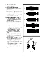
Reference
Pin
Catch
Reference Pin and
Catch have to
touch each other.
Part
A
Fig. 2-33-3
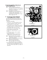
2-34.DRUM MOTOR STATOR, BRUSH
SPRING, SPACER, ROTOR CASE,
END RING, BRUSH, UPPER DRUM
ASSY
SET POSITION :
Normal
(Removal)
1. Disconnect the LEAD CONNECTOR of the DRUM
ASSY shown in the Fig. 2-34-1.
2. Remove the two screws (
a
) fastening the DRUM
MOTOR STATOR shown in the Fig. 2-34-1 to remove
the DRUM MOTOR STATOR.
3. Remove the two screws (
b
) fastening the ROTOR
CASE shown in the Fig. 2-34-1 to remove the ROTOR
CASE.
Note :
Mark on the END RING and UPPER DRUM ASSY
shown in the Fig. 2-34-1 using a pen, etc. for
convenience in installing them.
4. Loosen the hexagon screw (
c
) fastening the END
RING shown in the Fig. 2-34-1 to remove the END
RING.
5. Remove the BRUSH SPRING shown in the Fig. 2-34-
1.
6. Remove the BRUSH shown in the Fig. 2-34-1.
7. Remove the UPPER DRUM ASSY shown in the Fig.
2-34-1.
8. Remove the SPACER shown in the Fig. 2-34-1.
Содержание HS-HD1100U
Страница 54: ...LOCATIONS TP5A TP5B TPHSL TPHSR TP2H TP3Y PCB MAIN Component side REAR 2 PCB HEAD AMP Component side ...
Страница 57: ... 1 PARTS LIST 1 CABINET ASSEMBLY r 1 3 4 3 i o 0 2 6 t 7 2 1 ...
Страница 61: ...DECK ASSEMBLY ...
Страница 77: ......