


- 19 -
a
a
BRAKE BELT (TU)
BRAKE (TU)
REEL DISK (TU side)
Fig. 2-26
(Installation)
1. Apply GREASE (MULTEMP AC-DM) [859D055O90]
to the parts on the MAIN PLATE ASSY specified in
the Fig. 2-25.
2. Install the REEL DISK (SP side).
3. Install the TENS AXIS HOLDER.
Note :
Install the TENS AXIS HOLDER so that the catch
(
a
) for the TENSION ARM will be positioned on
the front (F/L ARM ASSY side).
4. Install the TENSION LEVER.
5. Install the TENSION ARM.
6. Install the TENSION SPRING.
Note :
Install the longer hook of the TENSION SPRING
to the TENSION ARM.
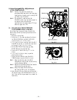
2-26.BRAKE BELT (TU)
SET POSITION :
Normal
Remove the following parts before replacing the BRAKE
BELT. Refer to the corresponding items to install them.
• STAY PLATE (Item 2-2)
• BOTTOM ASSY (Item 2-3)
(Removal)
1. Lift the BRAKE BELT (TU) shown in the Fig. 2-26 to
remove it from the REEL DISK (TU side).
2. Release the two catches (
a
) of the BRAKE (TU)
shown in the Fig. 2-26 to remove the BRAKE BELT
(TU).
(Installation)
1. Install the BRAKE BELT (TU) shown in the Fig. 2-26
to the BRAKE (TU).
2. Hook the BRAKE BELT (TU) shown in the Fig. 2-26 to
the REEL DISK (TU side).
Note :
Install the BRAKE BELT (TU) so that its Felt Side
touches the REEL DISK (TU side).
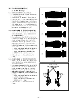
2-27.BRAKE (TU), REEL DISK (TU side)
SET POSITION :
Normal
Remove the following parts before replacing the BRAKE
(TU), REEL DISK (TU side). Refer to the corresponding
items to install them.
• STAY PLATE (Item 2-2)
• BOTTOM ASSY (Item 2-3)
• MOTOR HOLDER (Item 2-16)
• PINCH ARM CAP (Item 2-17)
• PINCH UNIT (Item 2-17)
• BRAKE CAM PLATE (Item 2-19)
(Removal)
1. Move the BRAKE (TU) in the Fig. 2-27 in the direction
shown by the arrow
A
to remove it.
2. Remove the BRAKE BELT (TU) from the BRAKE
(TU).
3. Remove the REEL DISK (TU).
A
BRAKE BELT (TU)
REEL DISK (TU side)
WASHER
BRAKE (TU)
MAIN PLATE
ASSY
GREASE
(MULTEMP AC-DM)
Fig. 2-27
Содержание HS-HD1100U
Страница 54: ...LOCATIONS TP5A TP5B TPHSL TPHSR TP2H TP3Y PCB MAIN Component side REAR 2 PCB HEAD AMP Component side ...
Страница 57: ... 1 PARTS LIST 1 CABINET ASSEMBLY r 1 3 4 3 i o 0 2 6 t 7 2 1 ...
Страница 61: ...DECK ASSEMBLY ...
Страница 77: ......


