


Chapter 3 Precautions for Use
3–6
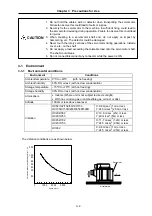
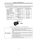
3-2-3 Tolerable load of axis
There is a limit to the load that can be applied on the shaft. Make sure that the load applied in the radial
direction and thrust direction, when mounted on the machine, is below the tolerable values given below.
These loads also affect the motor output torque, so consider them when designing the machine.
Servomotor
Tolerable radial load
Tolerable thrust load
HC52T, 102T, 152T
HC53T, 103T, 153T
Tapered shaft
392N (40kgf),
L=58
490N (50kgf)
HC52S, 102S, 152S
HC53S, 103S, 153S
Straight shaft
980N (100kgf), L=55
490N (50kgf)
HC202S, 352S, 452S,702S
HC203S, 353S, 453S, 703S
2058N (210kgf), L=79
980N (100kgf)
HC902S
2450N (250kgf), L=85
980N (100kgf)
HC103RT, 153RT, 203RT
Tapered shaft
392N (40kgf),
L=58
196N (20kgf)
HC103RS, 153RS, 203RS
Straight shaft
686N (70kgf),
L=45
196N (20kgf)
HA353RS, 503RS
980N (100kgf), L=63
392N (40kgf)
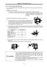
Caution:
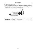
The symbols in the table follow the drawing below.
L
Thrust load
Radial load
L : Length from flange installation surface to center of load weight [mm]
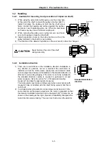
CAUTION
1. When coupling with a ball screw, etc., use a flexible coupling, and keep the
shaft core deviation to below the tolerable radial load.
2. When directly installing the gears on the motor shaft, the radial load will
increase as the gear diameter decreases. Consider this when designing the
machine.
3. When directly installing a pulley on the motor shaft, make sure that the radial
load (double the tension) generated from the timing belt tension is less than
the values in the above table.
4. In a machine having a thrust load, such as a worm gear, provide a separate
bearing on the machine side so that the a load exceeding the tolerable thrust
load is not applied on the motor.
5. Do not use a rigid coupling as an excessive bending load will be applied on
the shaft and could cause the shaft to break.


