Page 14
MODEL: WT-42313 / WT-42413
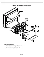
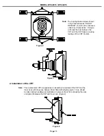
1. Carefully position the replacement CRT and fasten in place using 4 screws "c". [Figure 2]
2. Install the Deflection Yoke on the CRT neck. [Figure 3]
3. Install the Lens that was removed in step 5 of Removal of the CRT.
a) Position the Lens so that the Lens Adjustment Set Screw faces the rear of the TV [Figure 5].
b) Install the Lens mounting screws “b”. [Figure 1]
4. Insert the Optical Unit into the Light Box Assemblyand secure it with 4 screws “a” [Figure 1]..
5. Plug in the PCB-CRTs.
6. Insert the Anode Lead Wires into the Flyback Transformer.
7. Re-clamp the Lead Wire in its original position.
Figure 5
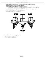
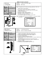
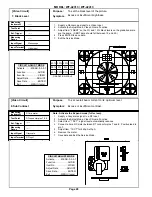
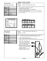
Adjustment procedures after replacing the CRT(s)
• CRT Cut Off / White Balance Adjustment
• Static Convergence Adjustment
• Dynamic Convergence Adjustment
Содержание WT-42313
Страница 2: ......
Страница 11: ...MODEL WT 42313 WT 42413 Page 11 PCB Locations Major Parts Locations ...
Страница 53: ...MODEL WT 42313 WT 42413 Page 53 POWER SUPPLY ...
Страница 54: ...MODEL WT 42313 WT 42413 Page 54 VIDEO COLOR ...
Страница 55: ...MODEL WT 42313 WT 42413 Page 55 SYNC SIGNAL PATH ...
Страница 56: ...MODEL WT 42313 WT 42413 Page 56 DEFLECTION HV ...
Страница 57: ...MODEL WT 42313 WT 42413 Page 57 HV REGULATION ...
Страница 58: ...MODEL WT 42313 WT 42413 Page 58 X RAY PROTECT ...
Страница 59: ...MODEL WT 42313 WT 42413 Page 59 SOUND SIGNAL PATH ...
Страница 60: ...MODEL WT 42313 WT 42413 Page 60 CONVERGENCE ...
Страница 61: ...MODEL WT 42313 WT 42413 Page 61 CONTROL CIRCUITRY ...
Страница 62: ...MODEL WT 42313 WT 42413 Page 62 ...


