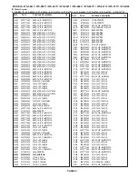
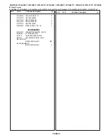
Mitsubishi Electric WS-B55 Скачать руководство пользователя страница 65

PAGE 65

Ref #

Part #

Part Name & Description

[#]

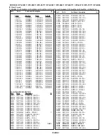
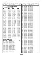
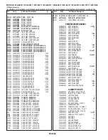
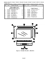
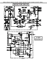
MODELS: WS-48511 / WS-55511 / WS-55711 / WS-65511 / WS-65611 / WS-65711 / WS-65712 / WS-73711 / WS-B55

[#] Model Legend:
(1) WS-B55, (2)  WS-48511, (3) WS-55511, (4) WS-55711, (5) WS-65511, (6) WS-65611, (7) WS-65711, (8) WS-65712,  (9) WS-73711

Ref #

Part #

Part Name & Description

[#]

C2V07

181P352050

C-ELEC - 16V 220M-M

C2V43

181P355060

C-ELEC - 50V 22M-M

C2V54

181P355050

C-ELEC - 50V 10M-M

C2V72

181P352050

C-ELEC - 16V 220M-M

C2W04

181P352050

C-ELEC - 16V 220M-M

C2W05

181P352030

C-ELEC - 16V 47M-M

C2W09

181P352030

C-ELEC - 16V 47M-M

C2W14

181P352030

C-ELEC - 16V 47M-M

C2X01

181P352040

C-ELEC - 16V 100M-M

C2X03

181P352030

C-ELEC - 16V 47M-M

C2Y01

181P352030

C-ELEC - 16V 47M-M

C2Y11

181P352030

C-ELEC - 16V 47M-M

C2Y30

181P352030

C-ELEC - 16V 47M-M

C3A10

181P355020

C-ELEC -  50V 2.2M-M

C3A11

181P352040

C-ELEC - 16V 100M-M

C3A15

181P124020

C-ELEC-NP - 50V 4.7M-M NP

C3A16

181P355050

C-ELEC - 50V 10M-M

C3A17

181P355050

C-ELEC - 50V 10M-M

C3A22

181P355050

C-ELEC - 50V 10M-M

C3A24

181P355040

C-ELEC - 50V 4.7M-M

C3A27

181P352060

C-ELEC - 16V 330M-M

C3A29

181P355050

C-ELEC - 50V 10M-M

C3A30

181P352040

C-ELEC - 16V 100M-M

C3A34

181P355050

C-ELEC - 50V 10M-M

C3A35

181P355040

C-ELEC - 50V 4.7M-M

C3A36

181P355040

C-ELEC - 50V 4.7M-M

C3A37

181P355040

C-ELEC - 50V 4.7M-M

C3A38

181P124020

C-ELEC-NP - 50V 4.7M-M NP

C3E01

181P354050

C-ELEC - 35V 47M-M

C3E02

181P355010

C-ELEC - 50V 1M-M

C3E04

181P355010

C-ELEC - 50V 1M-M

C3E06

181P355050

C-ELEC - 50V 10M-M

C3E07

181P353090

C-ELEC - 25V 2200M-M

C3E09

172P262050

C-M-POLY - 50V 0.1M-J

C3E11

172P262050

C-M-POLY - 50V 0.1M-J

C3E12

172P262050

C-M-POLY - 50V 0.1M-J

C3E14

172P262050

C-M-POLY - 50V 0.1M-J

C4A00

181P355050

C-ELEC - 50V 10M-M

C4A04

172P262050

C-M-POLY - 50V 0.1M-J

C4A05

172P262050

C-M-POLY - 50V 0.1M-J

C4A10

181P352030

C-ELEC - 16V 47M-M

C4A14

181P352030

C-ELEC - 16V 47M-M

C4A34

181P352030

C-ELEC - 16V 47M-M

C4A35

172P262090

C-M-POLY - 50V 0.22M-J

C4B01

172P262050

C-M-POLY - 50V 0.1M-J

C4B02

181P358000

C-ELEC - 35V 1000M-M

C4B03

172P383030

C-M-POLY - 100V 0.47M-K

C4B04

181P354060

C-ELEC - 35V 100M-M

C4B06

181P353020

C-ELEC - 25V 10M-M

C4B09

181P355060

C-ELEC - 50V 22M-M

C4B10

181P355070

C-ELEC - 50V 33M-M

C4B11

181P353090

C-ELEC - 25V 2200M-M

C4B13

172P262020

C-M-POLY - 50V 0.056M-J

C5102

181P355010

C-ELEC - 50V 1M-M

C5112

181P355010

C-ELEC - 50V 1M-M

C5122

181P355010

C-ELEC - 50V 1M-M

C51K7

181P351050

C-ELEC - 10V 220M-M

C51P1

181P350050

C-ELEC - 6.3V 470M-M

C5221

181P353060

C-ELEC - 25V 330M-M SO

C5234

181P355090

C-ELEC - 50V 100M-M

C5235

181P355090

C-ELEC - 50V 100M-M

C5251

181P351070

C-ELEC - 10V 470M-M

C5253

181P351060

C-ELEC - 10V 330M-M

C5255

181P351060

C-ELEC - 10V 330M-M

C5257

181P350060

C-ELEC - 6.3V 1000M-M

C5258

181P350050

C-ELEC - 6.3V 470M-M

C5291

181P353060

C-ELEC - 25V 330M-M SO

C5292

181P353060

C-ELEC - 25V 330M-M SO

C5295

181P353060

C-ELEC - 25V 330M-M SO

C5297

181P353060

C-ELEC - 25V 330M-M SO

C52F4

181P352040

C-ELEC - 16V 100M-M

C52G5

181P352040

C-ELEC - 16V 100M-M

C52G6

181P355010

C-ELEC - 50V 1M-M

C5305

181P350040

C-ELEC - 6.3V 330M-M

C54K2

189P197020

C-ELE-DOUBLE-LA - FM0H473Z/EECS5R5T473Z

C55C2

181P351040

C-ELEC - 10V 100M-M

C55C3

181P351040

C-ELEC - 10V 100M-M

C55C4

181P351040

C-ELEC - 10V 100M-M

C5612

181P122070

C-ELEC-NP - 25V 10M-M

C5617

181P122070

C-ELEC-NP - 25V 10M-M

C56A1

172P264010

C-M-POLY - 50V 2.2M-J

C56A2

172P264010

C-M-POLY - 50V 2.2M-J

C56A9

181P355020

C-ELEC -  50V 2.2M-M

C5902

181P350050

C-ELEC - 6.3V 470M-M

C59A6

181P351070

C-ELEC - 10V 470M-M

C59E0

181P350060

C-ELEC - 6.3V 1000M-M

C59E2

181P350050

C-ELEC - 6.3V 470M-M

C59M0

181P351070

C-ELEC - 10V 470M-M

C59X0

181P353060

C-ELEC - 25V 330M-M SO

C59X2

181P352020

C-ELEC - 16V 33M-M

C59X3

181P352020

C-ELEC - 16V 33M-M

C59X4

181P352020

C-ELEC - 16V 33M-M

C59X5

181P352020

C-ELEC - 16V 33M-M

C59X6

181P352020

C-ELEC - 16V 33M-M

C5A03

142P020050

C-CER - B50V 470P-K

C5A04

172P261030

C-M-POLY - 50V 0.01M-J

C5A10

181P191000

C-ELEC - 160V 22M-M/Q

C5A11

181P354060

C-ELEC - 35V 100M-M

C5A13

181P352040

C-ELEC - 16V 100M-M

C5A14

181P354060

C-ELEC - 35V 100M-M

C5A15

181P354060

C-ELEC - 35V 100M-M

C5A21

172P262050

C-M-POLY - 50V 0.1M-J

C5A22

181P355040

C-ELEC - 50V 4.7M-M

C5A23

181P355050

C-ELEC - 50V 10M-M

C5A31

172P580050

C-M-PLA-PP - 1800V 1500P-J

C5A32

172P581030

C-M-PLA-PP - 1800V 3300P-J

C5A33

172P581030

C-M-PLA-PP - 1800V 3300P-J

C5A34

154P262000

C-CER - R2KV 220P-K

C5A35

142P011070

C-CER - B500V 2200P-K

C5A36

172P524010

C-M-POLY - 250V 2.2M-J

C5A39

142P011000

C-CER - B500V 560P-K

C5A40

142P011000

C-CER - B500V 560P-K

C5A41

181P353080

C-ELEC - 25V 1000M-M

C5A42

181P352030

C-ELEC - 16V 47M-M

C5A43

181P190050

C-ELEC - 160V 1M-M/Q

C5A51

154P260010

C-CER - R1KV 220P-K

C5A52

172P460010

C-M-PLA-PP - 2000V 1000P-J

C5A53

172P460030

C-M-PLA-PP - 2000V 1200P-J

C5A54

185D120010

C-ELEC - H160V 330M-M 105C

C5A55

172P088060

C-PLAST-PP - 630V 6800P-J

Содержание WS-B55

Страница 1: ...RST 75Ω unbalanced COMP Y Cr Cb RCAType Y 1 0 Vp p Cr Cb 700mVp p ATV Y G Pr R Pb B H V Y 1 0Vp p with sync 75Ω BNC Pr Pb 700mV 75Ω H V 3 0Vp p 75Ω VGA R G B V H 15 pin D Output Level VIDEO OUT JACK RCA Type 1 0Vp p 75Ω unbalanced AUDIO OUT JACK RCAType 4 7dBm 4 7kΩ unbalanced Digital Interface IEEE 1394 I O Jacks AC 3 Digtal Audio Output V21 MODELS WS 48511 WS 55511 WS 65511 WS B55 V21 MODELS WS ...

Страница 2: ......

Страница 3: ...WS 65611 WS65711 WS 65712 WS 73711 17 Lenticular Screen and Fresnel Lens Installation 18 SERVICING THE DIAMONDSHIELDSTM r DiamondShield TM Removal Installation 19 CABINET SEPARATION 65 and 73 inch WS 65712 20 WS 65511 21 WS 65611 WS 65711 WS 73711 21 SERVICING PCBs Chassis and DM Module Removal 22 PCB Locations 23 Main Components Location 23 DM Module Main Components Location 24 CRTREPLACEMENT CRT...

Страница 4: ...LACEMENT 52 REPLACEMENT PARTS Parts Ordering 53 Critical and Warranty Parts Designation 53 Parts Tolerance Codes 53 Quick Reference List 54 Service Parts List 55 Screen Parts List 70 CIRCUITRY BLOCK DIAGRAMS Standby Supplies Regulator 74 Switched Supplies Regulator 75 DM Power Supply 76 Video Color A V Switch Circuit 77 Video Color Signal Path 78 Sync Signal Path 79 Deflection HV 80 X Ray Protect ...

Страница 5: ...d block diagrams of the above listed models are included in this service manual for better under standing of the circuitry PCB drawings are also included for easy location of parts and test points PRODUCT SAFETY NOTICE Many electrical and mechanical parts in television receivers have special safety related characteristics These characteristics are often not evident from visual inspection nor can t...

Страница 6: ...mponent with regard to X Radiation High voltage must be set as prescribed under the section titled Electrical Adjustments Leakage current check Before returning the receiver to the customer it is recommended that leakage current be measured according to the following methods 1 Cold Check With the alternating current AC plug removed from the AC source place a jumper across the two AC plug prongs Co...

Страница 7: ...ET DISASSEMBLY FRONT VIEW WS 48511 Refer to the Parts List for Part Numbers Front Cabinet Disassembly 1 Remove the Speaker Grille by pulling forward 2 Remove the Board Front by removing screws a 3 Remove the screws b holding the Screen Assembly 4 Lift the Screen Assembly up and away from the cabinet ...

Страница 8: ...r Cabinet Disassembly 1 Remove the Back Board by removing screws a and b 2 Remove 4 screws c securing the Board Slide 3 Remove 4 screws d holding each Board Shelf 4 Be certain that all cables and connectors between the Light Box Assembly and external items are disconnected e g speaker plugs etc 5 Remove 3 screws c and screw f Then slide the Light Box Assembly from the cabinet ...

Страница 9: ...MBLY FRONT VIEW WS B55 WS 55511 WS 65511 Refer to the Parts List for Part Numbers Front Cabinet Disassembly 1 Remove the Speaker Grille by pulling forward 2 Remove the Board Front by removing 4 screws a 3 Remove the 4 screws b holding the Screen Assembly 4 Lift the Screen Assembly up and away from the cabinet ...

Страница 10: ... 65611 Refer to the Parts List for Part Numbers Front Cabinet Disassembly 1 Remove the Speaker Grille by pulling forward 2 Remove the Board Front by removing screws b 3 Remove the Control Panel by removing two screws a 4 Remove the four screws c holding the Screen Assembly 5 Lift the Screen Assembly up and away from the cabinet ...

Страница 11: ... WS 73711 Refer to the Parts List for Part Numbers Front Cabinet Disassembly 1 Remove the Speaker Grilles and Unit Front by pulling forward 2 Remove 2 screws a to remove the Control Panel 3 Remove the Board Front by removing 4 screws b 4 Remove the 4 screws c holding the Screen Assembly 5 Lift the Screen Assembly up and away from the cabinet ...

Страница 12: ...rt Numbers Rear Cabinet Disassembly 1 Remove screws a holding the Back Board 2 Remove 4 screws a holding the Board Slide 3 Remove the 4 screws b holding each Board Shelf 4 Remove screw e and 3 screws c securing the Light Box Assembly 5 Be certain that all cables and connectors between the Light Box Assembly and external items are disconnected e g speaker plugs etc 6 Slide the Light Box out the rea...

Страница 13: ...rs Front Cabinet Disassembly 1 Remove the Speaker Grille by pulling forward 2 Remove 2 screws a securing the Front Panel 3 Slide the Front Panel 1 2 inch to the right then pull away from the TV 4 Remove 6 screws b to remove the Board Front 5 Unplug the LF connector 6 Remove the 4 screws c securing the Screen Assembly 7 Lift the Screen Assembly up and away from the cabinet ...

Страница 14: ...the Parts List for Part Numbers Rear Cabinet Disassembly 1 Remove screws a and b holding the Back Board 2 Remove the 4 screws c holding each Board Slike 3 Remove the 3 screws c and screw e securing the Light Box Assembly 4 Disconnect cabling to the front panel Control Panel Speakers Inputs etc 4 Slide the Light Box out the rear of the Cabinet ...

Страница 15: ...ause fire and heat related injuries WS 48511 Lenticular Screen and Fresnel Lens Removal 1 Remove the screen assembly shown in the Cabinet Disassembly procedure 2 Remove the Top Bottom and Side Screen Holders 3 Carefully lift the Lenticular Screen and Fresnel Lens combination from the Screen Frame assembly Note When separating the Lenticular Screen from the Fresnel Lens use caution while prying the...

Страница 16: ... may cause fire and heat related injuries WS B55 WS 55511 WS 65511 Lenticular Screen and Fresnel Lens Removal 1 Remove the screen assembly shown in the Cabinet Disassembly procedure 2 Remove the screws a securing the Screen Holder 3 Slide the Lenticular Screen and Fresnel Lens from the Screen Frame Note When separating the Lenticular Screen from the Fresnel Lens use caution while prying the Screen...

Страница 17: ...711 WS 65712 WS 73711 Lenticular Screen and Fresnel Lens Removal 1 Remove the screen assembly shown in the Cabinet Disassembly procedure 2 Remove the Screen Frame top section by removing 4 screws a 3 Carefully grasp the Lenticular Screen and Fresnel Lens combination and pull upward and out of the Screen Frame Assembly Note When separating the Lenticular Screen from the Fresnel Lens use caution whi...

Страница 18: ...enticular Screen and Fresnel Lens 1 Apply double coated tape Part LENS TAPE along the top front edge of the Fresnel Lens as shown below Refer to the Table below for proper tape length 2 Place the Fresnel Lens on top of the Lenticular Screen and apply pressure at the top edge to bond them together as shown below Model Screen Size Tape Length WS 48511 48 41 76 WS B55 55 47 8 WS 55511 55 56 5 WS 5571...

Страница 19: ...of the Shield and pull the Shield slightly away from the unit Place your hands at the points shown and gently bow the Shield toward you and remove from the unit Then re install the two clips Top Bottom Molding Clips Side Molding Clips 1 Gently insert a small screwdriver between the DiamondShield and one end of the clip to pry the clip loose 2 Remove both clips by pulling them toward you 3 Carefull...

Страница 20: ...ker Grille by pulling forward 2 Remove the two Front Cover screws a 3 To remove the Front Cover slide to the right approximately 1 2 then pull away from the TV Figure 2 4 Remove Screw b from the front board 5 Disconnect the LF connector Figure 3 6 Remove screw c on each side of the cabinet 7 Remove the plastic cover on each side Figure 4 8 Slide the top of the cabinet top forward Figure 5 9 Carefu...

Страница 21: ...ft the cabinet top and place it on the floor 5 Place the cabinet bottom in the desired loca tion 6 Reverse the procedure and mount the cabinet top on the cabinet bottom 7 Reinstall the the Screen Assembly and connect all cable harnesses between the Screen Assembly and the PCB SIGNAL WS 65611 WS 65711 WS 73711 WS 65611 WS 65711 WS 73711 Cabinet Separation Precedure 1 Remove the 4 screw covers a 2 R...

Страница 22: ...peakers CRTs etc 2 Remove screw a securing the Main Chassis and screws b in model WS 65712 3 Release the Chassis Locks on each side of the chassis 3 Slide the Chassis and DM Module out the rear of the unit 5 Tilt upward to access the bottom of the main chassis NOTE If the chassis cannot be removed with the DM Module due to insufficient cable length 1 Perform Step 1 through 3 above 2 Remove 1 screw...

Страница 23: ...Page 23 MODELS WS 48511 WS 55511 WS 55711 WS 65511 WS 65611 WS 65711 WS 65712 WS 73711 WS B55 PCB Locations Main Components Location ...

Страница 24: ...Page 24 MODELS WS 48511 WS 55511 WS 55711 WS 65511 WS 65611 WS 65711 WS 65712 WS 73711 WS B55 DM POWER SUPPLY ATV TUNER DE MODULATOR E2P MODULE FLASH CARD SLOT COVER DM Module Main Components Location ...

Страница 25: ...y 2 Remove the Back Board 3 Remove the Anode Lead Wire from the CR Block 4 Remove the PCB CRT 5 Remove 4 hex screws a retaining the Optical Unit Figure 5 1 6 Remove 4 screws b retaining the Lens Note DO NOT loosen the RED screws Doing so will break the seal between the C Element and the 6 Lens causing leakage of the CRT Coolant 7 Remove 4 screws c retaining the CRT Figure 5 2 8 Remove the Deflecti...

Страница 26: ...e space between them filled with ethylene glycol Care should be taken during handling and installation to prevent shock from disrupting the seal or alignment between the CRT and Inner Lens Figure 5 3 Note The CRT fixing screws should not be loosened nor should they be removed Figure 5 4 1 Carefully position the replacement CRT and fasten in place using 4 screws d Figure 5 6 Figure 5 6 Figure 5 5 F...

Страница 27: ...the Lens so that the Label faces the direction shown in Figure 5 8 b Install the mounting screws Figure 5 1 4 Connect the PCB CRT 5 Insert the Optical Unit into the Light Box Assembly 6 Insert the Anode Lead Wire into the Flyback Transformer 7 Re clamp the Lead Wire in its original position Adjustment procedures after replacing the CRT s CRT Cut Off White Balance Adjustment Static Convergence Adju...

Страница 28: ...quipment Oscilloscope Unless otherwise specified use 10 1 probes Signal Generator both SD and HD capable Frequency Counter Direct Current Voltmeter Direct Current Power Supply Multiplex Audio Signal Generator Direct Current Ampere Meter Test Signal A Monoscope Signal Note If you do not have a monoscope signal source connect the unit to a VCR and play a Monoscope alignment tape Part Number 859C5680...

Страница 29: ...N A N A Level Sound OFF OFF OFF OFF OFF OFF OFF A V RESET DEFAULT SETTINGS By Input Edit Setup Closed Captions With Mute Volume 30 Review CC Background Gray Bass 50 Antenna A Enabled Digital Channel Guide On Treble 50 Antenna B Enabled Balance 50 Antenna DTV Enabled V CHIP Off Surround Off Input DTV Enabled TV Rating TV PG Listen to Stereo Input 1 Enabled FV Fantasy Violence Enabled Level Sound Of...

Страница 30: ... The LED then flashes indicating the value of the LSD ones digit of the Error Code The Error Code is repeated a total of 5 times Example If the Error Code is 24 the LED will flash two times pause and then flash four times 3 Error Codes The Error Code designations indicating a malfunction or no malfunction are listed below Remote Control Operational Modes There are two Remote Hand Unit Operational ...

Страница 31: ...ode does not appear on screen B Selection of adjustment Functions and Adjustment Items To select an adjustment item in the circuit adjustment mode first select the adjustment function that includes the specific adjustment item to be selected Then select the adjustment item Refer to the following pages for the listing of adjustment functions and adjustment items 1 Press the AUDIO button on a remote...

Страница 32: ...ctivation 1 Press MENU 2 1 5 9 2 When the Convergence Mode is activated this display appears on a Green Crosshatch B Selecting the HD or SD Mode 1 Select the Signal Source before entering the Convergence Mode either an NTSC or HD source 2 Enter the Convergence Mode If the signal source is NTSC the SD mode is activated If the signal source is HD the HD mode is activated 3 Activating the HD mode whe...

Страница 33: ... with the AUDIO button FINE GREEN a Green Crosshatch is displayed to make Fine Raster Corrections FINE RED a White Crosshatch is displayed to make Fine Red Convergence Adjustments FINE BLUE a White Crosshatch is displayed to make Fine Blue Convergence Adjustments Cursor In the Fine mode a Cursor is added to the Crosshatch The ENTER button toggles the Cursor between two modes MOVE blinking Cursor u...

Страница 34: ...al Data Notes NO Abbrev Description Range 480i 480p 1080i VGA 1 SCT Picture Gain H Temp 0 63 42 42 42 42 Sub Contrast 2 SBRT Sub Brightness H Temp 0 63 26 26 26 26 Black Level 3 SCOL Sub Color H Temp 0 15 7 5 3 3 Preset 4 STIN Sub Tint 0 15 6 10 15 7 5 SCON Sub Contrast H Temp 0 15 2 3 3 3 6 RDRH R Drive high 0 63 30 30 30 30 White Balance 7 GDR G Drive 0 63 35 35 35 35 Preset 8 BDRH B Drive high ...

Страница 35: ...tem Abbrev Description Range RF Non RF 1 TNTM Main Tint 0 63 24 24 Preset 2 COLM Main Color 0 63 17 17 3 YDRM Main Gain Control 0 31 5 5 Main Y Level 4 VPDM Pr Pedestal Adjustment 0 15 7 7 5 UPDM Pb Pedestal Adjustment 0 15 7 7 Initial Data DYNAMIC FOCUS MENU 2 1 5 9 Item Number Abbrev Name Data SD HD 1 DFH Dynamic Focus Horizontal 500 2 DFV Dynamic Focus Vertical 100 Description OSD Horizontal Ce...

Страница 36: ...0 0 0 4 TILT Tilt X axix rotation 0 0 0 0 0 0 0 0 5 HLIN Horixontal Linearity 190 190 180 170 150 150 220 190 6 HWID Horizontal Width 0 10 0 0 10 10 10 10 7 VKEY Vertical Keystone Correction 120 110 100 95 90 70 100 110 8 VWID Vertical Height 0 0 0 0 0 0 0 0 9 VLIN Vertical Linearity 0 0 0 0 0 0 0 0 10 TPPC Top Bottom PC Correction 20 20 20 20 20 20 20 20 11 SDBW Horizontal Side Bow 30 30 30 30 30...

Страница 37: ...712 WS 73711 WS B55 Page 37 Adjustment Test Point Location Test Points DT pin 3 HV Adjust DT pin 6 Ground DT pin 7 12 Volts DT pin 8 ACL EA pin 1 Sub Picture Y EA pin 15 Main Picture Y EB pin 5 POP Cr ST pin 12 Left Audio ST pin 16 Right Audio TP6 R G or B CRT Cathode ...

Страница 38: ...12 Left Audio 7 Confirm that the left audio level at pin 12 of the ST connector is 1 56 Vp p 0 06V 550mv 20mv rms Note Adjustment 2 Stereo Separation must be performed after this adjustment Audio Circuit 1 MCS Input Level Oscilloscope Conector ST pin 16 10mV Div RF Stereo RF Input Audio Circuit 2 Separation Check stereo separation Poor stereo separation Note This adjustment must follow Adjustment ...

Страница 39: ...re than 0 15V Note This adjustment must be performed if E2RESET or Convergence E2RESET are activated HV Circuit 3 HV Regulation Oscilloscope EA connector pins 15 1 Color Bars Video Input Video Circuit 4 Main Sub Y Level To set picture luminance Excess or insufficient brightness 1 Supply a color bar signal to a Video Input not an RF input 2 Select the color bar signal for both the main and sub pict...

Страница 40: ... is short adjust Items 4 VPDS and 5 UPDS 5 Side by Side Sub Picture Tint To set the sub picture color level Main and sub pictures color levels differs Video Circuit 6 Side by Side Sub Color Oscilloscope EB connector pin 5 200mV div 20usec div Color Bars Video Input Note Let the set run for at least one minute before making this adjustment 1 Supply a color bar signal 2 Select the color bar signal a...

Страница 41: ... To set the CRTs white level in the NTSC mode Monochrome has a color tint Note Use the FORMAT button to activate the Expand mode full screen 1 Supply a full White Raster Signal 2 Activate the Service Mode VC function 3 Set the data for Item 23 COL to 0 4 Adjust Items 6 RDRH and 8 BDRH for optimum white at the center of the screen 5 Reduce the input luminance level to 25 6 Adjust Items 9 CTRH and 1...

Страница 42: ...6 RDRH and 8 BDRH for optimum white at the center of the screen 6 Reduce the input signal luminance to 25 7 Adjust Items 9 CTRH and 11 CTBH for optimum white 8 Set the data for Item 23 COL back to 31 White Raster HD NTSC Video DTV Inputs CRT Circuit 10 Cb Cr Offset To set Cb and Cr color signal level Incorrect colors 1 Supply an NTSC White Raster 25 luminance signal to a Video Input 2 Activate the...

Страница 43: ...ON SCALE DC ma meter DT connector pins 7 8 Grayscale RF Input To set overall beam current to its optimum level Excess or insufficient contrast Note Activate the Expand mode full screen 1 Supply a Grayscale signal to a RF Input 2 Activate the Adjust Mode VC Function 3 Select Item 1 SCT signal level automatically reduces 4 Connect a 3ma DC meter between DT connector pins 7 and 8 Positive lead to pin...

Страница 44: ...e CONV MISC Table 5 Exit the Conv Mode Monoscope Video Input Poor focus Note This adjustment must be done before Electrostatic Focus Perform this adjustment for RED GREEN and BLUE monochrome pictures 1 Supply a VIDEO signal Monoscope 2 Cover the Red and Blue Lens producing a green raster 3 Adjust the Green Lens for best focus at the center of the Monoscope pattern Note Attach a white paper to the ...

Страница 45: ...tic Focus Alignment Magnet To set electrostatic focus to the optimum point Poor focus Note This adjustment must be performed after the Sub Contrast adjustment Alignment Magnet Adjustment WS 55711 65611 65711 65712 73711 Only This adjustment must be performed before Static Focus Adjustment 1 Supply a Crosshatch with Center Dot signal to a Video Input 2 Set the display format to Standard Format butt...

Страница 46: ...0 0 0 0 0 0 9 TBPC 150 150 200 190 200 170 220 180 10 VKEY 15 10 15 10 0 0 10 10 11 VWID 0 0 0 0 0 0 0 0 12 VLIN 0 0 0 0 0 0 0 0 CONV RED MENU 2 1 5 9 5 No Abbrev SD HD SD HD SD HD SD HD 1 HSTA 50 50 50 50 50 50 50 50 2 VSTA 0 0 0 0 0 0 0 0 3 SKEW 0 0 0 0 0 0 0 0 4 TILT 0 0 0 0 0 0 0 0 5 HLIN 190 190 180 170 150 150 220 190 6 HWID 0 10 0 0 10 10 10 10 7 VKEY 120 110 100 95 90 70 100 110 8 VWID 0 0...

Страница 47: ...SC Monoscope signal to a Video Input 2 Select the Monoscope as the signal source 3 Activate the Adjustment Mode JNGL Function 4 Select and adjust each of the following items 7 VHGT so the vertical marker sum 4 1 HWD so the horizontal marker sum 7 5 Save data and Exit the Service Mode HD Mode 1 Supply an HD Monoscope signal to the DTV HD Inputs 2 Select the DTV Inputs as the signal source Input but...

Страница 48: ...te the Convergence Mode Coarse Green 3 Adjust the Coarse Green Items shown below for straight crosshatch lines 4 Select the Fine Green Mode a Cursor is displayed on the crosshatch 5 Use the Cursor to adjust for straight crosshatch lines 6 Exit the Convergence Mode HD mode 1 Supply horizontal and vertical HD sync to the DTV Inputs and select the DTV Inputs as the source Note If an HD signal is not ...

Страница 49: ...the Coarse Green mode Center the Green Raster using the Green Centering Magnet Rotate the Green Deflection Yoke to correct any tilt 6 In the Coarse Red mode use the Red Centering Magnet to converge red on the green at the center of screen Correct any red tilt with the Red Deflection Yoke 7 In the Coarse Blue mode repeat Step 6 using the Blue Centering magnet and the Blue Deflection Yoke 8 Exit the...

Страница 50: ...the Items shown below to converge the red on the green 4 Select Coarse Blue mode 5 Adjust the Items shown below to converge the blue on the green Note If center convergence shifts use red and blue Items 0 HSTA and 1 VSTA to correct the shift 6 Exit the Convergence Mode HD mode 1 Supply horizontal and vertical HD sync to the DTV Inputs and select the DTV Inputs as the source Note If an HD signal is...

Страница 51: ...ence Mode Fine Red 3 Use the Cursor to converge red on the green 4 Select the Fine Blue mode 5 Use the Cursor to converge blue on the green 6 Exit the Convergence mode HD Fine Adjustment 1 Supply an HD signal sync only to the DTV inputs and select DTV with the Audio button Note If an HD signal is not available select Ant DTV with no signal as the source 2 Repeat SD Fine Adjustment Steps 2 through ...

Страница 52: ...eat for more than 3 three seconds to new chip parts 5 Avoid using a rubbing stroke when soldering 6 Take care not to scratch or damage the chip parts when soldering 7 Supplementary cementing is not required Chip Parts Removal Resistors Capacitors etc 1 Grasp the part with tweezers Melt the solder at both sides alternately and remove one side of the part with a twisting motion 2 Melt the solder at ...

Страница 53: ...orders will result Critical and Warranty Parts Designation Critical Electrical Components are indicated by Bold Type in the Parts List and in the schematic diagrams by shading Warranty Return Parts are indicated in the Parts List with an Parts Tolerance Codes Refer to the following chart for tolerance characteristics of electrical components MARK B C D F G J K Tolerance 0 1 0 25 0 5 1 2 5 10 MARK ...

Страница 54: ...ANODE SHORT RED WS 73711 only 453B035040 CAP ANODE LONG G B WS 73711 only MODEL ASSY CRT RED ASSY CRT RED ASSY CRT RED WS 48511 251C222010 251C222020 251C222030 WS B55 251C221070 251C221080 251C221090 WS 55511 251C219040 251C219050 251C219060 WS 55711 251C219070 251C219080 251C219090 WS 65511 251C220010 251C220020 251C220030 WS 65611 251C220040 251C220050 251C220060 WS 65711 251C220070 251C220080 ...

Страница 55: ...OS TC74LCX08FT IC5290 270P677030 IC BAO9FP IC5300 275P684010 IC C MOS TL810B IC5300 669D544020 SCREW SEMS W M3X0 5 12 IC5301 275P672010 IC C MOS RM5231 200Q IC5302 275P675010 IC C MOS SN74LV125APWR IC5303 275P666010 IC C MOS MAX6358SYUT T IC53A0 275P741020 IC C MOS MT48LC8M16A2TG 75 IC53A1 275P741020 IC C MOS MT48LC8M16A2TG 75 IC53A2 275P741020 IC C MOS MT48LC8M16A2TG 75 IC53A3 275P741020 IC C MOS...

Страница 56: ...C MOS MSM534031E TS K IC7H04 270P506010 IC M51957BFP IC7H05 263P384010 IC C MOS TC74HC221AF EL IC7H06 270P348010 IC TLC2932IPW IC7H07 275P437020 IC SLA4028 IC7H08 270P348010 IC TLC2932IPW IC7H09 274P901010 IC C MOS TC74HCT7007AF EL IC7H11 275P535010 IC C MOS TC74AC157FN ELP IC7H12 275P535010 IC C MOS TC74AC157FN ELP IC7H13 275P535010 IC C MOS TC74AC157FN ELP IC7H14 275P535010 IC C MOS TC74AC157FN ...

Страница 57: ...U1A D5A51 262P039010 DIODE BYW96E 20 D5A52 264P899010 DIODE BYV26E D5A53 264P489010 DIODE RD16FB1 D5A54 264P724010 DIODE STF14 D5A55 264P724010 DIODE STF14 D5A56 264P045040 DIODE 1S24710M D5A57 264P521040 DIODE EU1A D5A58 264P045040 DIODE 1S24710M D5A59 264P045040 DIODE 1S24710M D5A60 264P489010 DIODE RD16FB1 D5F00 264P828010 D CHIP DAN202U MA142WK D5F01 264P828010 D CHIP DAN202U MA142WK D5F02 264...

Страница 58: ...42 409P777080 EMI F CHIP BLM21P221S L2M00 409P777080 EMI F CHIP BLM21P221S L2M20 409P777080 EMI F CHIP BLM21P221S L2V06 409P923060 EMI F CHIP BLM21B272S L2V72 409P923060 EMI F CHIP BLM21B272S L2V90 409P923060 EMI F CHIP BLM21B272S L2V95 409P923060 EMI F CHIP BLM21B272S L2W01 409P923060 EMI F CHIP BLM21B272S L2W02 409P923060 EMI F CHIP BLM21B272S L2W03 409P923060 EMI F CHIP BLM21B272S L2W04 409P923...

Страница 59: ... 325C141090 COIL CHIP 33MH K L59R0 325C141030 COIL CHIP 10MH K L59R3 325C141030 COIL CHIP 10MH K L59X0 325C140050 COIL CHIP 2 2MH M K J L5A31 411P001010 LEAD FERRITE L5A33 333P052030 COIL HORIZ LIN L5A34 321C130010 COIL RF 2MH L5A51 321C141030 COIL RF 10MH K L5A52 321C141030 COIL RF 10MH K L5A53 321C141010 COIL RF 6 8MH M L5A54 411D009020 CORE FERRITE L5A55 411D009020 CORE FERRITE L5F00 409P923060...

Страница 60: ...NF20C470S CKD510JB1H470S LC7E13 409P876020 EMI F CHIP CNF20C470S CKD510JB1H470S LC7E14 409P876020 EMI F CHIP CNF20C470S CKD510JB1H470S LC7G01 409P876020 EMI F CHIP CNF20C470S CKD510JB1H470S LC7G02 409P876020 EMI F CHIP CNF20C470S CKD510JB1H470S LC7G03 409P876020 EMI F CHIP CNF20C470S CKD510JB1H470S LC7G04 409P876020 EMI F CHIP CNF20C470S CKD510JB1H470S LC7G05 409P876020 EMI F CHIP CNF20C470S CKD51...

Страница 61: ...CARBON 1 4W 6 8K J R3E16 103P713050 R CARBON 1 4W 6 8K J R4B02 103P463060 R METAL 1 4W 3K F 2 R4B05 103P713090 R CARBON 1 4W 15K J R4B10 103C188050 R METAL 2W 2 7 J R4B12 103C188040 R METAL 2W 2 2 J R4B17 103P712010 R CARBON 1 4W 470 J R4B20 103P711090 R CARBON 1 4W 330 J R4B22 103P712090 R CARBON 1 4W 2 2K J 1345678 R4B23 103P711070 R CARBON 1 4W 220 J R4B24 103P712050 R CARBON 1 4W 1K J R4B25 10...

Страница 62: ...2W10K K R5K02 103P412050 R CARBON 1 4W 1K J R5K03 103P145000 R CARBON 1 2W 120K J R5K04 103P144090 R CARBON 1 2W 100K J R5K05 103P145000 R CARBON 1 2W 120K J R5K06 103P144090 R CARBON 1 2W 100K J R5K07 103P145000 R CARBON 1 2W 120K J R5K08 103P144090 R CARBON 1 2W 100K J R5K09 103P762020 R FUSE 1 2W 560 J R5K10 103P711010 R CARBON 1 4W 68 J R5K12 103P760060 R FUSE 1 2W 27 J R5K13 103P145000 R CARB...

Страница 63: ...CARBON 1 2W 180K J R9A05 109C010010 R COMPOSITION 1 2W1M K R9A06 109C010010 R COMPOSITION 1 2W1M K R9A09 103P144090 R CARBON 1 2W 100K J R9A10 103P713040 R CARBON 1 4W 5 6K J R9A11 103P144090 R CARBON 1 2W 100K J R9A12 103P713030 R CARBON 1 4W 4 7K J R9A20 103P713010 R CARBON 1 4W 3 3K J R9A21 103C393090 R METAL P 3W15K J R9A22 103C183070 R METAL 2W 10K J R9A23 103P710070 R CARBON 1 4W 33 J R9A24 ...

Страница 64: ... 16V100M M C1A30 181P352040 C ELEC 16V100M M C1A31 181P352040 C ELEC 16V100M M C1A50 172P262010 C M POLY 50V 0 047M J C1B10 181P355090 C ELEC 50V100M M C1B29 181P352040 C ELEC 16V100M M C1B30 181P352040 C ELEC 16V100M M C1B31 181P352040 C ELEC 16V100M M C1B50 172P262010 C M POLY 50V 0 047M J C2A00 181P352030 C ELEC 16V47M M C2A50 181P352030 C ELEC 16V47M M C2A51 181P352030 C ELEC 16V47M M C2A60 18...

Страница 65: ...10 C ELEC 50V1M M C5122 181P355010 C ELEC 50V1M M C51K7 181P351050 C ELEC 10V220M M C51P1 181P350050 C ELEC 6 3V470M M C5221 181P353060 C ELEC 25V330M MSO C5234 181P355090 C ELEC 50V100M M C5235 181P355090 C ELEC 50V 100M M C5251 181P351070 C ELEC 10V470M M C5253 181P351060 C ELEC 10V330M M C5255 181P351060 C ELEC 10V330M M C5257 181P350060 C ELEC 6 3V1000M M C5258 181P350050 C ELEC 6 3V470M M C52...

Страница 66: ... C7K01 181P352030 C ELEC 16V47M M C7K21 181P355050 C ELEC 50V10M M C7K23 181P352030 C ELEC 16V47M M C7K25 172P262050 C M POLY 50V 0 1M J C7K26 172P262050 C M POLY 50V 0 1M J C7K27 181P355010 C ELEC 50V1M M C7K28 181P355050 C ELEC 50V10M M C7L22 172P262050 C M POLY 50V 0 1M J C8C03 181P184010 C ELEC 50V1000M M105C C8C05 181P184010 C ELEC 50V1000M M105C C8C43 142P020080 C CER B50V 820P K C8C44 142P0...

Страница 67: ...250VAC0 1M M C9D01 189P153040 C M POLY 250VAC0 1M M CF2E00 299P128010 CERAMIC OSC CSB500F2 CF2H01 299P128010 CERAMIC OSC CSB500F2 CF3A01 299P208010 CERAMIC OSC C5B503F58 SWITCHES S5400 432C082010 SW PUSH SPPJ322300 S7L20 432P089010 SW KEY BOARD PUSH SWITCH S7L21 432P089010 SW KEY BOARD PUSH SWITCH S7L22 432P089010 SW KEY BOARD PUSH SWITCH S7L23 432P089010 SW KEY BOARD PUSH SWITCH S7L24 432P089010 ...

Страница 68: ...2A20 285P029030 QUARTZ CRYST 4 000 MHZ X2B20 285P029030 QUARTZ CRYST 4 000 MHZ X2C31 285P374050 QUARTZ CRYST 20 000MHZ X2E26 285P374020 QUARTZ CRYST 3 579545MHZ X2H26 285P066010 QUARTZ CRYST 3 579545MHZ X50 285P410060 QUARTZ CRYST 26 800MHZ X51X0 285P410020 QUARTZ CRYST 24 576MHZ X5400 285P410050 QUARTZ CRYST 9 216MHZ X54A0 285P410040 QUARTZ CRYST 25 0MHZ X5500 285P410030 QUARTZ CRYST 20 25MHZ X55...

Страница 69: ...73711 Ref Part Part Name Description 761A186020 GRILLE SP RIGHT 73 9 761A195010 GRILLE SPEAKER 2 761A174030 GRILLE SPEAKER 4 761A174040 GRILLE SPEAKER 4 761A199010 GRILLE SPEAKER 8 752A003030 SPEAKER GRILL TOP PS 9 ACCESSORIES 290P109010 TRANSMITTER REMOTE EUR761 I B WSB55 IB OWNERS GUIDE I QR V21 QUICK REFERENCE GUIDE I NET V21 NET COMMAND GUIDE BOOK I SEP GUIDEV21 IB SEPARATIONGUIDE 5679 I SEPGU...

Страница 70: ...1 8 WS 65712 9 WS 73711 SCREENASSEMBLYPARTS WS 48511 Figure1 1 491P138010 SCREEN LENTICULAR 48 2 2 491P139010 LENS FRESNEL 48 2 3 622B010010 HOLDER TOP 2 4 622B011010 HOLDER BOTTOM 2 5 622B012010 HOLDER SIDE 2 6 622B013010 CLIP SHIELD SIDE 48 2 7 751A005020 FRAME SCREEN BEZEL PLASTIC 2 8 760D628060 DIAMOND SHIELD 48 2 9 598D339010 BRACKET SCREENSIDE METAL 2 10 635B109010 STIFFENER TOP METAL 2 Figu...

Страница 71: ...NEL 1 3 4 622C063040 HOLDER SCREEN BOT 1 3 5 701B454010 FRAMESCREEN TOP 55 1 3 6 701B457030 FRAME SCREEN S 55 1 3 7 702A388030 CAP CORNER LEFT 1 3 8 702A388040 CAP CORNER RIGHT 1 3 9 760D627060 DIAMOND SHIELD 55 3 9 760D639020 DIAMOND SHIELD 55 1 10 622C060040 CLIP SCREEN TOP BOT 1 3 WS 65511 Figure2 1 491P105030 SCREEN LENTICULAR 65W V21 5 2 491P106050 LENS FRESNEL 65W V21 5 3 702A393050 CONTROLP...

Страница 72: ... 73711 SCREENASSEMBLYPARTS WS 65712 Figure3 1 491P105040 SCREEN LENTICULAR LENTI 6 8 2 491P106060 LENS FRESNEL FRESNEL 65W 8 3 622C090010 CLIP SHIELD 65 8 4 702A408010 CAP CORNER METAL 8 5 702A409010 CAP CORNER BOTTOM METAL RIGHT 8 6 702A409020 CAP CORNER BOTTOM METAL LEFT 8 7 760D635020 DIAMOND SHIELD 8 8 701B466010 FRAME SIDE AL METAL 8 9 701B467010 FRAME TOP AL METAL 8 10 701B468010 FRAME BOTTO...

Страница 73: ... 491P106050 LENS FRESNEL 65W V21 6 3 5 701B429020 SCREEN FRAME TOP BOT 65 6 4 701B430020 SCREEN FRAME SIDE 65 6 6 760D627070 DIAMOND SHIELD 65 6 7 702A396010 CAP CORNERS 6 9 622C071020 CLIP SCREEN TOP BOT 6 WS 65711 Figure4 1 491P105030 SCREEN LENTICULAR 65W V21 7 2 491P106050 LENS FRESNEL 65W V21 7 3 711C026040 FRAME SCREEN TOP 65 7 4 711C026050 FRAME SCREEN SIDES 65 7 5 711C026060 FRAME SCREEN B...

Страница 74: ...MODELS WS 48511 WS 55511 WS 55711 WS 65511 WS 65611 WS 65711 WS 65712 WS 73711 WS B55 Page 74 STANDBY SUPPLIES REGULATOR ...

Страница 75: ...MODELS WS 48511 WS 55511 WS 55711 WS 65511 WS 65611 WS 65711 WS 65712 WS 73711 WS B55 Page 75 SWITCHED SUPPLIES REGULATOR ...

Страница 76: ...MODELS WS 48511 WS 55511 WS 55711 WS 65511 WS 65611 WS 65711 WS 65712 WS 73711 WS B55 Page 76 DM POWER SUPPLY ...

Страница 77: ...MODELS WS 48511 WS 55511 WS 55711 WS 65511 WS 65611 WS 65711 WS 65712 WS 73711 WS B55 Page 77 VIDEO COLOR A V SWITCH CIRCUIT ...

Страница 78: ...MODELS WS 48511 WS 55511 WS 55711 WS 65511 WS 65611 WS 65711 WS 65712 WS 73711 WS B55 Page 78 PCB SIGNAL Y C PATH ...

Страница 79: ...MODELS WS 48511 WS 55511 WS 55711 WS 65511 WS 65611 WS 65711 WS 65712 WS 73711 WS B55 Page 79 SYNC PATH ...

Страница 80: ...MODELS WS 48511 WS 55511 WS 55711 WS 65511 WS 65611 WS 65711 WS 65712 WS 73711 WS B55 Page 80 DEFLECTION CIRCUIT X RAY PROTECT ...

Страница 81: ...MODELS WS 48511 WS 55511 WS 55711 WS 65511 WS 65611 WS 65711 WS 65712 WS 73711 WS B55 Page 81 SOUND CIRCUIT ...

Страница 82: ...MODELS WS 48511 WS 55511 WS 55711 WS 65511 WS 65611 WS 65711 WS 65712 WS 73711 WS B55 Page 82 CONVERGENCE CIRCUIT ...

Страница 83: ...MODELS WS 48511 WS 55511 WS 55711 WS 65511 WS 65611 WS 65711 WS 65712 WS 73711 WS B55 Page 83 CONTROL CIRCUIT ...

Страница 84: ...ION TELEVISION V21 V21 V21 CHASSIS V21 MODELS WS 48511 WS 55511 WS 65511 WS B55 V21 MODELS WS 65611 WS 65611 PART 2 SCHEMATIC DIAGRAMS CONTENTS Page Overall PCB Block Diagram 1 PCB MAIN 2 PCB POWER 3 PCB POWER 4 PCB SIGNAL 1 AV I O 5 PCB SIGNAL 2 MICRO 6 PCB SIGNAL 3 VIDEO CHROMA 7 PCB 3DYC 8 PCBs CONV GEN JUNGLE 9 PCBs CONTROL CRT CROSSOVER DBF DM POWER FRONT PREAMP SVM 10 PCB 2HDW 1 11 PCB 2HDW ...

Страница 85: ......

Страница 86: ......

Страница 87: ......

Страница 88: ......

Страница 89: ......

Страница 90: ......

Страница 91: ......

Страница 92: ......

Страница 93: ......

Страница 94: ......

Страница 95: ......

Страница 96: ......

Страница 97: ......

Отзывы: