


Page 27
MODELS: WS-48511 / WS-55511 / WS-55711 / WS-65511 / WS-65611 / WS-65711 / WS-65712 / WS-73711 / WS-B55
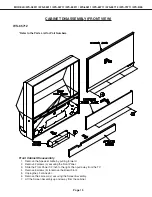
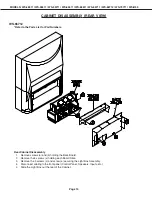
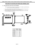
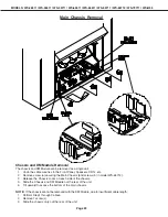
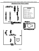
2. Install the Deflection Yoke on the CRT neck. [Figure 5-7]
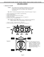
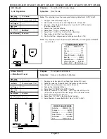
3. Install the Lens that was removed in steps 8 and 9 of Removal Of The CRT. [ Figures 5-1 and 5-2 ]
a) Position the Lens so that the Label faces the direction shown in Figure 5-8.
b) Install the mounting screws. [Figure 5-1]
4. Connect the PCB-CRT.
5. Insert the Optical Unit into the Light Box Assembly.
6. Insert the Anode Lead Wire into the Flyback Transformer.
7. Re-clamp the Lead Wire in its original position.
Adjustment procedures after replacing the CRT(s)
• CRT Cut Off / White Balance Adjustment
• Static Convergence Adjustment
• Dynamic Convergence Adjustment
Figure 5-7
Figure 5-8
Содержание WS-B55
Страница 2: ......
Страница 76: ...MODELS WS 48511 WS 55511 WS 55711 WS 65511 WS 65611 WS 65711 WS 65712 WS 73711 WS B55 Page 76 DM POWER SUPPLY ...
Страница 79: ...MODELS WS 48511 WS 55511 WS 55711 WS 65511 WS 65611 WS 65711 WS 65712 WS 73711 WS B55 Page 79 SYNC PATH ...
Страница 81: ...MODELS WS 48511 WS 55511 WS 55711 WS 65511 WS 65611 WS 65711 WS 65712 WS 73711 WS B55 Page 81 SOUND CIRCUIT ...
Страница 83: ...MODELS WS 48511 WS 55511 WS 55711 WS 65511 WS 65611 WS 65711 WS 65712 WS 73711 WS B55 Page 83 CONTROL CIRCUIT ...
Страница 85: ......
Страница 86: ......
Страница 87: ......
Страница 88: ......
Страница 89: ......
Страница 90: ......
Страница 91: ......
Страница 92: ......
Страница 93: ......
Страница 94: ......
Страница 95: ......
Страница 96: ......
Страница 97: ......