


Page 38
Purpose:
Measuring
Instrument
Test Point
Measuring
Range
Input Signal
Ext. Trigger
Input Terminal
Symptom:
Purpose
Measuring
Instrument
Test Point
Measuring
Range
Input Signal
Ext. Trigger
Input Terminal
Symptom:
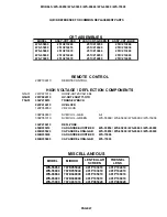
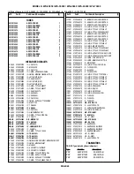
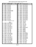
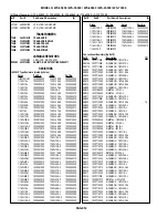
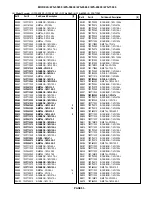
MODELS: WS-55859 / WS-55909 / WS-65869 / WS-65909 / WS-73909
-----
-----
------
------
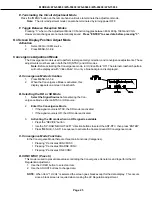
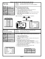
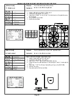
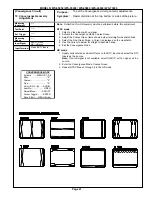
Video Signal (HD/NTSC)
ANT-A/DTV
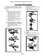
[On Screen Display]
16.Character Position
To position the character display horizontally.
Incorrect display position
1. Supply an NTSC signal to Ant-A and select Ant-A as the source.
2. Enter the OSD Position Mode, press MENU-0-1-8-8.
3. Adjust OSDSD to center the OSD horizontally.
4. Press MENU to save data and exit the mode.
5. Supply a HD signal to the DTV inputs and select the DTV Inputs as the source.
6. Enter the OSD Position Mode, press MENU-0-1-8-8.
7. Adjust OSDHD to center the OSD horizontally.
3. Press MENU to save data and exit the mode.
-----
-----
------
------
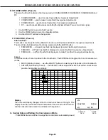
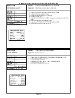
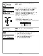
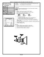
Monscope & Crosshatch
Video Input
[CRT Circuit]
15. Electrostatic Focus &
(Alignment Magnet)
To set electrostatic focus to the optimum point.
Poor focus.
Note:
This adjustment must be performed after the Sub Contrast adjustment.
Alignment Magnet Adjustment (WS-55909, WS-65909 and WS-73909 Only)
This adjustment must be performed before Static Focus Adjustment
1. Supply a Crosshatch with Center Dot signal to a Video Input.
2. Select a Green raster using the table below.
3. Roughly adjust Green Focus VR.
4. Rotate Green Focus VR CCW so the center dot is about 10mm diameter.
5. Adjust the Green 4 Pole Magnet for the roundest center dot.
6. Set the Green Focus VR for optimum focus.
7. Repeat the procedure with a Red raster and adjust the Red 4 Pole Magnet.
8. Use silicon to lock the magnets in place.
Static Focus Adjustment (All Models)
1. Supply a Monoscope signal to a Video Input
2. Activate A/V Reset
3. Select Red, Green or Blue rasters using the table below.
3. Set the Red, Green and Blue Focus VRs for optimum focus at the top center of
the picture..
Raster Color Selection
Color Raster Activation Code
Red
MENU-0-1-5-9-1
Green
MENU-0-1-5-9-2
Blue
MENU-0-1-5-9-3
Содержание WS-55859
Страница 2: ......
Страница 16: ...Page 16 MODELS WS 55859 WS 55909 WS 65869 WS 65909 WS 73909 PCB Locations Main Components Location ...
Страница 61: ...MODELS WS 55859 WS 55909 WS 65869 WS 65909 WS 73909 Page 61 STANDBY SUPPLIES REGULATOR ...
Страница 62: ...MODELS WS 55859 WS 55909 WS 65869 WS 65909 WS 73909 Page 62 SWITCHED SUPPLIES REGULATOR ...
Страница 63: ...MODELS WS 55859 WS 55909 WS 65869 WS 65909 WS 73909 Page 63 DM POWER SUPPLY ...
Страница 64: ...MODELS WS 55859 WS 55909 WS 65869 WS 65909 WS 73909 Page 64 VIDEO COLOR A V SWITCH CIRCUIT ...
Страница 65: ...MODELS WS 55859 WS 55909 WS 65869 WS 65909 WS 73909 Page 65 PCB SIGNAL Y C PATH ...
Страница 66: ...MODELS WS 55859 WS 55909 WS 65869 WS 65909 WS 73909 Page 66 SYNC PATH ...
Страница 67: ...MODELS WS 55859 WS 55909 WS 65869 WS 65909 WS 73909 Page 67 DEFLECTION CIRCUIT X RAY PROTECT ...
Страница 68: ...MODELS WS 55859 WS 55909 WS 65869 WS 65909 WS 73909 Page 68 SOUND CIRCUIT ...
Страница 69: ...MODELS WS 55859 WS 55909 WS 65869 WS 65909 WS 73909 Page 69 CONVERGENCE CIRCUIT ...
Страница 70: ...MODELS WS 55859 WS 55909 WS 65869 WS 65909 WS 73909 Page 70 CONTROL CIRCUIT ...
Страница 72: ......
Страница 73: ......
Страница 74: ......
Страница 75: ......
Страница 76: ......