


Page 30
Purpose:
Measuring
Instrument
Test Point
Measuring
Range
Input Signal
Ext. Trigger
Input Terminal
Symptom:
Purpose
Measuring
Instrument
Test Point
Measuring
Range
Input Signal
Ext. Trigger
Input Terminal
Symptom:
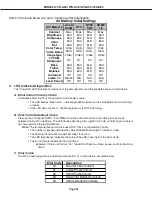
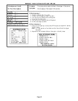
MODELS: VS-A50 / WS-A48 / WS-A55 / WS-A65
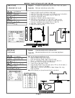
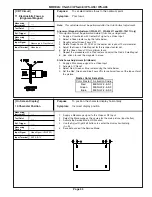
DC Voltmeter
DT connector pins 3 & 6
------
-------
Video Signal
Monoscope
Video Input
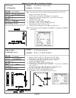
To set the CRT Anode voltage.
Dark Picture
Note:
This adjustment must be rechecked following Adjustment 9 CRT Cutoff.
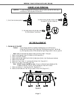
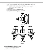
1. Supply a video monoscope signal.
2. Set Contrast to maximum, and Brightness to mid position.
3. Connect a DC volt meter between pins 3 and 6 of the DT connector.
(Positive lead to pin 3)
4. Activate the Conv-Misc Mode.
5. Select Item “1 HVOL” (screen goes black).
6. Adjust Item “1 HVOL” for 15.4V ±0.05V on the meter.
7. Save data and exit the Conv-Misc mode.
8. Confirm that the voltage does not change more than 0.15V.
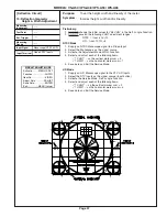
Note:
This adjustment must be performed if E2RESET or Convergence E2RESET
are activated.
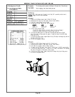
[HV Circuit]
1. HV Regulation
Oscilloscope
JA Connector pin 17
JB Connector pin 1
------
------
Color Bars
Video Input
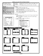
[Video Circuit]
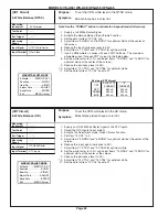
2. Main/Sub Y Level
To set picture luminance
Excess or insufficient brightness.
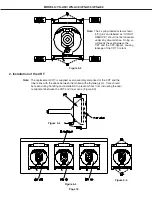
1. Supply a color bar signal to a Video Input (not an RF input).
2. Select the color bar signal for both the main and sub pictures.
3. Connect the oscilloscope to connector JA pin 17 (Main-Y).
4. Activate the Adjustment Mode
5. Select Item “3 YDRM” in the Main Matrix function.
6. Adjust the data so the Main-Y signal is between 0.71 Vp-p max. and 0.66 Vp-p
min. at JA pin 17.
(If it cannot be adjusted within this range, set to the lower value)
7. Move the oscilloscope to connector JB pin 1 (Sub-Y).
8. Select Item “3 YDRS” in the Sub Matrix function.
9. Adjust the data to equal the MAIN-Y Gain (+0.0V -0.1V).
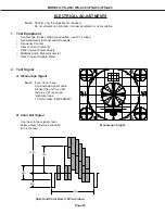
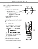
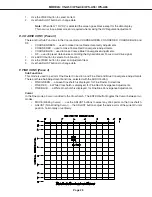
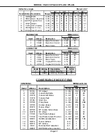
CONVERGENCE MODE
Activate ……..MENU-2-2-5-9
Misc. ……………….……"6"
Coarse………………..…."5"
Fine ……………………..."4"
Color (R,G or B)……AUDIO
Item No………….…..VIDEO
Adjust/Move……….ADJUST
Cursor Toggle….…..ENTER
Save & Exit…..MENU (twice)
CIRCUIT ADJUST MODE
Activate …….. MENU-2-2-5-7
Function …...………..AUDIO
Item No. ……….…….VIDEO
Adjust Data ….…….ADJUST
Save Data …. ………ENTER
Exit …………..MENU (twice)
Содержание VS-A50
Страница 2: ......
Страница 58: ...Page 58 MODELS VS A50 WS A48 WS A55 WS A65 POWER SUPPLY ...
Страница 59: ...Page 59 MODELS VS A50 WS A48 WS A55 WS A65 VIDEO COLOR PATH ...
Страница 60: ...Page 60 MODELS VS A50 WS A48 WS A55 WS A65 SYNC PATH ...
Страница 61: ...Page 61 MODELS VS A50 WS A48 WS A55 WS A65 DEFLECTION HV CIRCUIT ...
Страница 62: ...Page 62 MODELS VS A50 WS A48 WS A55 WS A65 X RAY PROTECT ...
Страница 63: ...Page 63 MODELS VS A50 WS A48 WS A55 WS A65 HV REGULATION ...
Страница 64: ...Page 64 MODELS VS A50 WS A48 WS A55 WS A65 SOUND PATH ...
Страница 65: ...Page 65 MODELS VS A50 WS A48 WS A55 WS A65 CONVERGENCE CIRCUIT ...
Страница 66: ...Page 66 MODELS VS A50 WS A48 WS A55 WS A65 CONTROL CIRCUIT ...


