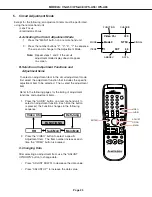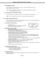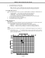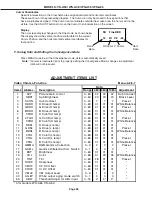
Page 22
MODELS: VS-A50 / WS-A48 / WS-A55 / WS-A65
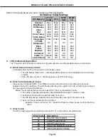
Items in the table below are set to following after Initalization.
4.
LED Indicator Diagnostics
The “Power ON LED” provides an indication of the sets operation, and the possible cause of a malfunction.
A. Initial Control Circuitry Check
Immediately after the TV is connected to an AC power source:
•
The LED flashes three times ... indicating the Microprocessor has initialized and is functioning
properly.
•
If the LED does not flash ... the Microprocessor is NOT functioning.
B. Error Code Operational Check
Pressing the front panel “INPUT” and “MENU” buttons at the same time, and holding for 5 seconds,
activates the Error Code Mode. The LED flashes denoting a two digit Error Code, or indicating no problem
has occured since the last Initalization.
Note:
The front panel buttons must be used, NOT those on the Remote Control.
•
The number of flashes indicates the value of the MSD (tens digit) of the Error Code.
•
The flashing then pauses for approximately 1/2 second.
•
The LED then flashes indicating the value of the LSD (ones digit) of the Error Code.
•
The Error Code is repeated a total of 5 times.
Example: If the Error Code is “24”, the LED will flash two times, pause, and then flash four
times.
C. Error Codes
The Error Code designations indicating a malfunction, or no malfunction, are listed below:
Error Code
Description
12
No error has occurred.
21
X-Ray Protect circuit.
22
Short Protect circuit.
23
Horizontal Deflection failure.
24
Vertical Deflection failure.
A/V Memory
Ant-A
Ant-B
DTV
NTSC
1/2/3
COMP.
1/2
Contrast
Max
Max
Max
Max
Brightness
Mid
Mid
Mid
Mid
Sharpness
Mid
Mid
Mid
Mid
Color
Mid
Mid
Mid
Mid
Tint
Mid
Mid
Mid
Mid
Color Temp.
High
High
High
High
Video Noise
Stnd.
Stnd.
Stnd.
Stnd.
Image type
Video
Video
Video
Video
TV VSM
Sharpness
On
On
On
On
Bass
Mid
Mid
Mid
Mid
Treble
Mid
Mid
Mid
Mid
Balance
Mid
Mid
Mid
Mid
Surround
Off
Off
Off
Off
Listen To
Stereo
N/A
N/A
N/A
Level Sound
Off
Off
Off
Off
AV Memory Initial Settings
Содержание VS-A50
Страница 2: ......
Страница 58: ...Page 58 MODELS VS A50 WS A48 WS A55 WS A65 POWER SUPPLY ...
Страница 59: ...Page 59 MODELS VS A50 WS A48 WS A55 WS A65 VIDEO COLOR PATH ...
Страница 60: ...Page 60 MODELS VS A50 WS A48 WS A55 WS A65 SYNC PATH ...
Страница 61: ...Page 61 MODELS VS A50 WS A48 WS A55 WS A65 DEFLECTION HV CIRCUIT ...
Страница 62: ...Page 62 MODELS VS A50 WS A48 WS A55 WS A65 X RAY PROTECT ...
Страница 63: ...Page 63 MODELS VS A50 WS A48 WS A55 WS A65 HV REGULATION ...
Страница 64: ...Page 64 MODELS VS A50 WS A48 WS A55 WS A65 SOUND PATH ...
Страница 65: ...Page 65 MODELS VS A50 WS A48 WS A55 WS A65 CONVERGENCE CIRCUIT ...
Страница 66: ...Page 66 MODELS VS A50 WS A48 WS A55 WS A65 CONTROL CIRCUIT ...

