Mitsubishi Electric TM-RF004C20 Скачать руководство пользователя страница 46

44

7  TM-RFM SERIES
7.2  Specification list

*1 When the power supply voltage drops, the output and the rated speed cannot be guaranteed.
*2 If the load to motor inertia ratio exceeds the indicated value, contact your local sales office.
*3 To configure the absolute position detection system, connect to a battery unit and an absolute position storage unit. Refer to the 

following for the absolute position storage unit.

Page 41 Absolute position storage unit MR-BTAS01

For the battery, refer to "Battery" in the following manual.

MR-J5 User's Manual (Hardware)

*4 The shaft-through portion of the rotor and the connector area are excluded. IP classifies the degree of protection provided against the 

intrusion of solid objects and water in electrical enclosures.

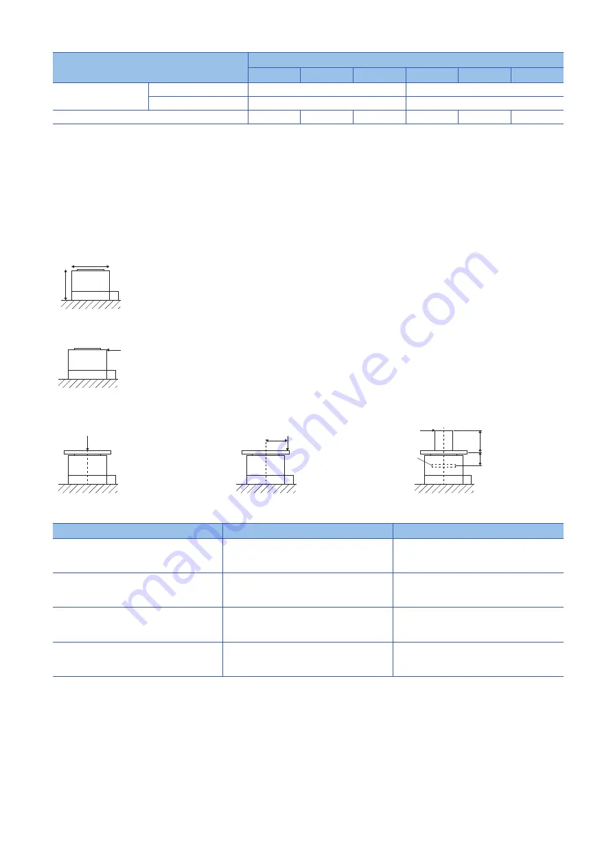
*5 The vibration direction is as shown in the figure. The numerical value indicates the maximum value. When the direct drive motor stops, 

fretting is likely to occur at the bearing. Therefore, suppress the vibration to about half of the permissible value.

*6 V10 indicates that the amplitude of a direct drive motor as a single unit is 10 

μ

m or less. The following figure shows the direct drive motor 

mounting position for measurement and the measuring position.

*7 The axial and moment loads, which are applied to the direct drive motor's rotor (output shaft) during operation, must be maintained to be 

equal to or below the permissible value. The following figure shows an example of the load applied during operation.

*8 The absolute accuracy changes depending on the mounting condition of the load and the surrounding environment.

Rotor permissible load 

*7

Moment load [N•m]

93

350

Axial load [N]

5500

16000

Mass [kg]

17

36

52

53

91

146

Direct drive motor

Motor OD [mm]

Dimension A [mm]

TM-RFM002C20
TM-RFM004C20
TM-RFM006C20

φ

130

19.1

TM-RFM006E20
TM-RFM012E20
TM-RFM018E20

φ

180

20.2

TM-RFM012G20
TM-RFM048G20
TM-RFM072G20

φ

230

24.4

TM-RFM040J10
TM-RFM120J10
TM-RFM240J10

φ

330

32.5

Item

TM-RFM series

012G20

048G20

072G20

040J10

120J10

240J10

X

Y

Measuring position

F

L F

L

A

(External force)

(External force)

Axial load = F + mass of load

Axial load = F + mass of load
Moment load = F × L

Axial load = mass of load
Moment load = F × (L + A)

F (External force)

Bearings

Содержание TM-RF004C20

Страница 1: ...Direct Drive Motor User s Manual TM RFM TM RG2M TM RU2M Mitsubishi Electric AC Servo System ...

Страница 2: ......

Страница 3: ... Please follow the instructions of both levels because they are important to personnel safety Forbidden actions and required actions are indicated by the following diagrammatic symbols In this manual precautions for hazards that can lead to property damage instructions for other functions and other information are shown separately in the POINT area After reading this manual keep it accessible to t...

Страница 4: ...y To prevent an electric shock any person who is involved in wiring should be fully competent to do the work To prevent an electric shock do not attempt to wire the direct drive motor until it has been mounted To prevent an electric shock do not touch the conductive parts Precautions To prevent injury do not touch the rotor of the direct drive motor during operation To prevent injury transport the...

Страница 5: ...used safely The manuals used differ depending on the interface of the servo amplifier For details refer to the User s Manual Introduction CABLES USED FOR WIRING Cables mentioned in this manual are selected based on an ambient temperature of 40 C Rotary Servo Motor Linear Servo Motor Direct Drive Motor Partner Encoder Function Adjustment Object Dictionary Troubleshooting This manual is necessary pr...

Страница 6: ...values if necessary according to the following table Quantity SI metric unit U S customary unit Mass 1 kg 2 2046 lb Length 1 mm 0 03937 inch Torque 1 N m 141 6 oz inch Moment of inertia 1 10 4 kg m2 5 4675 oz inch2 Load thrust load axial load 1 N 0 2248 lbf Temperature N C 9 5 32 N F ...

Страница 7: ... Parts with a service life 14 2 8 Machine accuracy 14 2 9 Flange size 15 2 10 Magnetic shielding 15 CHAPTER 3 CONNECTORS USED FOR DIRECT DRIVE MOTOR WIRING 16 3 1 Selection of connectors 16 3 2 Wiring connectors connector configurations A B C D E F 17 CHAPTER 4 CONNECTOR DIMENSIONS 20 CHAPTER 5 CONNECTING THE SERVO AMPLIFIER AND DIRECT DRIVE MOTOR 25 5 1 Precautions for wiring 26 5 2 Direct drive ...

Страница 8: ... RG2M SERIES TM RU2M SERIES 52 8 1 Model designation 52 8 2 Specification list 53 TM RG2M RU2M series 53 8 3 Torque characteristics 55 8 4 Derating 55 Restrictions on the ambient temperature 56 Restrictions on the altitude 56 8 5 Installation method 57 8 6 Dimensions 58 TM RG2M002C30 58 TM RG2M004E30 58 TM RG2M009G30 59 TM RU2M002C30 59 TM RU2M004E30 60 TM RU2M009G30 60 CHAPTER 9 COMPLIANCE WITH E...

Страница 9: ...FM series Page 46 Derating TM RG2M series TM RU2M series Page 55 Derating 3 Refer to the following for restrictions on using this product at an altitude exceeding 1000 m and up to 2000 m TM RFM series Page 46 Derating TM RG2M series TM RU2M series Page 55 Derating 4 Do not place the direct drive motor near magnetic sources such as magnets When it is necessary to use the motor near magnetic sources...

Страница 10: ...eriod and conditions If the servo motor is to be stored for longer than six months apply rust prevention oil again especially to the machined surfaces of the rotor or other parts Before using the product after an extended storage hand turn the rotor output shaft of the direct drive motor and check to ensure that there is no abnormality When the product has been stored for an extended period of tim...

Страница 11: ... motor mounted on the machine A great vibration may cause early damage to a bearing and encoder The great vibration may also cause the poor connector connection or screw looseness For the gain adjustment at the equipment startup check the torque waveform and the speed waveform with a measurement device to check that no vibration occurs If the vibration occurs due to high gain the vibration may cau...

Страница 12: ...talled to a machine Precautions for Z phase mark passing After power on the Z phase mark of the direct drive motor must pass the connector area once In a system which prevents the direct drive motor from making a full rotation or more install the direct drive motor in a position where the Z phase mark can pass over the connector area To make the Z phase mark pass the connector area the Z phase mar...

Страница 13: ...o amplifier s power supply from off to on If the direct drive motor can be rotated manually make the Z phase mark pass over the connector area while only the servo amplifier s control circuit power supply is on After that switch the servo amplifier s power supply from off to on If the direct drive motor cannot be rotated manually detect the magnetic poles while the torque is balanced then run the ...

Страница 14: ...rmissible load for the rotor Do not use rigid coupling as it may damage the rotor For the permissible rotor load specific to the direct drive motor refer to the following Page 43 Specification list When coupling a load to the direct drive motor the load applied to the rotor must be within the permissible load Exceeding the permissible load can cause the deterioration of the bearing life and damage...

Страница 15: ... direct drive motor is exposed to oil mist steam oil water grease and or the like a standard specification direct drive motor cannot be used Provide dust proof and waterproof measures on the machine side 2 6 Inspection items Precautions To prevent a malfunction do not perform an insulation resistance test megger test on the direct drive motor Customers must not disassemble and or repair the equipm...

Страница 16: ... accuracy The following table indicates the machine accuracy of the rotor output shaft and the mounting area of the direct drive motor except special products Reference diagram Part name Recommended service life Remark Bearings 20 000 hours to 30 000 hours The service lives in the Recommended service life column are reference times If any fault is found before this time is reached the part must be...

Страница 17: ...er factors Make sure that alarms do not occur on the actual machine before operation 2 10 Magnetic shielding Do not place the direct drive motor near magnetic sources such as magnets When it is necessary to use the motor near magnetic sources block the magnetic force by installing a shielding plate or other blocking agents Flange size mm Direct drive motor 400 400 20 TM RG2M002C30 TM RU2M002C30 TM...

Страница 18: ... the direct drive motor Refer to the following for the compatible connector configuration products Page 17 Wiring connectors connector configurations A B C D E F 1 Used in the absolute position detection system Direct drive motor Wiring connector For power supply For encoder Absolute position storage unit option 1 Servo amplifier side Encoder side TM RFM_C20 Connector configuration B Connector con...

Страница 19: ...vo amplifier side 1 Type Plug Cord clamp Model Cable OD mm reference A IP67 Straight RM15WTPZK 12S JR13WCCA 8 72 20276 VSVPAWG 23 6P KB 0492 2 8 2 RM15WTRZB 12P 72 Connector configuration Feature Plug DDK Cable clamp Direct drive motor power supply connector 2 Type Model Cable OD mm reference Model B IP67 EN compliant Straight CE05 6A14S 2SD D Applicable wire size AWG 22 to 16 4 to 8 ACS 08RL MS14...

Страница 20: ...ess Bushing ID D MS3057 10A Connector configuration Feature Plug DDK Cable clamp DDK Direct drive motor power supply connector 2 Type Model Cable OD mm reference Model D IP67 EN compliant Straight CE05 6A22 22SD D BSS Applicable wire size AWG 10 to 8 9 5 to 13 CE3057 12A 2 D CE05 2A22 22PD D 12 5 to 16 CE3057 12A 1 D General environment 1 D MS3106B22 22S Applicable wire size AWG 10 to 8 15 9 or le...

Страница 21: ...er Toa Electric Industrial Co Ltd Nagoya Branch Connector configuration Feature Plug Hirose Electric Recommended cable Bando Densen Absolute position storage unit connector encoder side 1 Type Plug Cord clamp Model Cable OD mm reference F IP67 Straight RM15WTPZ 12P 72 JR13WCCA 8 72 20276 VSVPAWG 23 6P KB 0492 2 8 2 RM15WTRZB 12S 72 Plug Cord clamp ...

Страница 22: ...ion Page 17 Wiring connectors connector configurations A B C D E F JR13WCCA 8 72 Refer to the following connector configurations A and F for the connector configuration Page 17 Wiring connectors connector configurations A B C D E F Model Connector configuration 1 RM15WTPZK 12S A RM15WTPZ 12P 72 F M19 1 M16 0 75 36 3 φ21 5 φ15 2 Spanner hook gap dimension 18 Unit mm 7 5 φ20 M16 0 75 8 Spanner hook ...

Страница 23: ...e connector configuration Page 17 Wiring connectors connector configurations A B C D E F Model A C 0 8 D or less W Connector configuration 1 CE05 6A18 10SD D BSS 1 1 8 18UNEF 2B 34 13 32 1 57 1 20UNEF 2A C CE05 6A22 22SD D BSS 1 3 8 18UNEF 2B 40 48 38 3 61 1 3 16 18UNEF 2A D CE05 6A32 17SD D BSS 2 18UNS 2B 56 33 54 2 79 1 3 4 18UNS 2A E 24 0 1 8 46 0 5 5 6 0 1 7 8 20UNEF 2B 13 2 3 4 20UNEF 2A φ28 ...

Страница 24: ...5 9 14 1 31 7 1 20UNEF 2B CE3420 10 1 10 5 to 14 1 C CE3057 10A 2 D 11 0 CE3420 10 2 8 5 to 11 CE3057 12A 1 D 22 23 8 35 10 3 41 3 19 16 0 37 3 1 3 16 18UNEF 2B CE342012 1 12 5 to 16 D CE3057 12A 2 D 13 0 CE342012 2 9 5 to 13 CE3057 20A 1 D 32 27 8 51 6 11 9 43 0 32 0 23 8 51 6 1 3 4 18UNS 2B CE3420 20 1 22 0 to 23 8 E Model A J L Q V W Y Connector configuration 1 D MS3106B14S 2S 7 8 20UNEF 13 49 ...

Страница 25: ...57 10A 18 23 8 30 1 10 3 15 9 14 3 31 7 1 20UNEF AN3420 10 C D MS3057 12A 22 23 8 35 0 10 3 19 0 15 9 37 3 1 3 16 18UNEF 2A AN3420 12 D D MS3057 20A 32 27 8 51 6 11 9 31 7 23 8 51 6 1 3 4 18UNS AN3420 20 E Model Applicable cable OD A Length L before tightening Width across flats D Width across corners D1 Width across flats D2 Width across corners D3 Connector configuration 1 YSO14 5 to 8 4 to 8 3 ...

Страница 26: ...tors connector configurations A B C D E F Model Screw C Applicable cable OD A φd Tightening nut Nipple body L L1 Connector configuration 2 E Two face width F Width across corners G Number of corners E Two face width F Width across corners G Number of corners ACS 08RL MS14F 3 4 20UNE F 2B 4 0 to 8 0 7 15 0 20 22 0 6 22 24 2 6 46 41 B ACS 12RL MS14F 3 4 20UNE F 2B 8 0 to 12 0 7 15 0 24 26 4 6 36 28 ...

Страница 27: ...Do not connect a magnetic contactor or the like between the servo amplifier power output and the direct drive motor power input When the wires are not properly secured to the terminal block the wires or terminal block may generate heat because of the poor contact Be sure to secure the wires with the specified torque Use the direct drive motor with the specified servo amplifier Do not modify the eq...

Страница 28: ...rive motor connect the grounding lead wire to the servo amplifier then connect the wire from the servo amplifier to the ground via the protective earth PE terminal of the cabinet Do not connect the wire directly to the protective earth PE terminal of the cabinet 5 2 Direct drive motor power cable wiring diagram To wire to the servo amplifier use connectors packed with the servo amplifier or option...

Страница 29: ...amples for the 600 V Grade heat resistant polyvinyl chloride insulated wire HIV wire are indicated below TM RFM series TM RG2M series and TM RU2M series Direct drive motor Wire mm2 U V W E TM RFM002C20 1 25 AWG 16 TM RFM004C20 TM RFM006C20 TM RFM006E20 TM RFM012E20 TM RFM018E20 TM RFM012G20 TM RFM048G20 3 5 AWG 12 TM RFM072G20 TM RFM040J10 1 25 AWG 16 TM RFM120J10 3 5 AWG 12 TM RFM240J10 5 5 AWG 1...

Страница 30: ...used for previous generation direct drive motors 6 1 Connector set For the connectors used with this direct drive motor please purchase the options indicated in this section When fabricating an encoder cable refer to the following Page 64 Fabricating the encoder cable Precautions The indicated IP rating is the connector s protection against ingress of dust and water when the connector is connected...

Страница 31: ...t Page 41 Absolute position storage unit MR BTAS01 For the battery refer to Battery in the following manual MR J5 User s Manual Hardware 4 4 5 1 2 3 6 CNP3 CN2 TM RFM TM RG2M TM RU2M MR BTAS01 2 CN4 7 6 CN2 CN4 1 Encoder connector Power connector For incremental system For absolute position detection system For absolute position detection system Absolute position storage unit MR J5 1 axis servo am...

Страница 32: ...refer to Battery in the following manual MR J5 User s Manual Hardware 2 This connection is for the MR J5 3 axis servo amplifier 4 4 5 1 2 3 TM RFM TM RG2M TM RU2M MR BTAS01 1 2 2 CNP3A CNP3B CNP3C CN2B CN2A CN2C CN4 CN4 Encoder connector Power connector For incremental system For absolute position detection system For absolute position detection system Absolute position storage unit Direct drive m...

Страница 33: ...P67 EN compliant 3 Power connector set MR PWCNS5 Plug CE05 6A22 22SD D BSS Cable clamp CE3057 12A 1 D DDK Applicable cable Applicable wire size 5 5 mm2 to 8 mm2 AWG 10 to 8 Cable OD 12 5 mm to 16 mm For the TM RFM040J10 For the TM RFM120J10 IP67 EN compliant 4 Encoder connector set MR J3DDCNS For connection between servo amplifier and direct drive motor For connection between servo amplifier and a...

Страница 34: ...ge unit Refer to the following for the absolute position storage unit Page 41 Absolute position storage unit MR BTAS01 For the battery refer to Battery in the following manual MR J5 User s Manual Hardware MR J3DDCNS This connector set is used to fabricate an encoder cable for the incremental system or the absolute position detection system between the servo amplifier and the absolute position stor...

Страница 35: ...ition detection system between the absolute position storage unit and the direct drive motor Applicable wire size 0 25 mm2 to 0 5 mm2 AWG 23 to 20 Absolute position storage unit side connector Plug RM15WTPZ 12P 72 Cord clamp JR13WCCA 8 72 Hirose Electric Encoder side connector Plug RM15WTPZK 12S Cord clamp JR13WCCA 8 72 Hirose Electric ...

Страница 36: ... following for details Page 38 Detail of the encoder cable C connector 3 This connection is for the MR J5 3 axis servo amplifier 4 If the distance exceeds 20 m contact your local sales office CN2B CN2A CN2 CN2C 1 2 TM RFM TM RG2M TM RU2M 2 Or MR J5 multi axis servo amplifier MR J5 1 axis servo amplifier Encoder cable A 1 50 m or less Direct drive motor CN2B CN2A CN2 CN2C 3 4 TM RFM TM RG2M TM RU2M...

Страница 37: ...t are marked with a diagonal line Refer to the following Page 40 Shielding CN2 CN2A CN2B and CN2C connectors Encoder side connector 2 Straight plug RM15WTPZK 12S Cord clamp JR13WCCA 8 72 Hirose Electric Recommended cable 20276 VSVPAWG 23 6P KB 0492 2 Bando Densen The following shows the view from the wiring side 1 1 Do not connect anything to the pins that are marked with a diagonal line 2 Supplie...

Страница 38: ... Connector set 54599 1019 Molex The following shows the view from the wiring side 1 1 Do not connect anything to the pins that are marked with a diagonal line Refer to the following Page 40 Shielding CN2 CN2A CN2B and CN2C connectors Core size mm2 Conductor resistance of one core Ω km Cable OD mm 0 25 63 6 or less 8 2 P5 LG 1 2 MR MRR 3 4 6 9 5 7 8 10 LG MR MRR P5 THM1 THM1 11 6 THM2 THM2 5 FG SD ...

Страница 39: ...mp JR13WCCA 8 72 Hirose Electric Recommended cable 20276 VSVPAWG 23 6P KB 0492 2 Bando Densen The following shows the view from the wiring side 1 1 Do not connect anything to the pins that are marked with a diagonal line 2 Supplier Toa Electric Industrial Co Ltd Nagoya Branch 1 MRR BAT 3 5 4 2 MR 7 6 12 THM1 9 8 P5 LG 10 11 FG THM2 ...

Страница 40: ...ug RM15WTPZ 12P 72 Cord clamp JR13WCCA 8 72 Hirose Electric Recommended cable 20276 VSVPAWG 23 6P KB 0492 2 Bando Densen The following shows the view from the wiring side 1 1 Do not connect anything to the pins that are marked with a diagonal line 2 Supplier Toa Electric Industrial Co Ltd Nagoya Branch Core size mm2 Conductor resistance of one core Ω km Cable OD mm 0 25 63 6 or less 8 2 P5 LG 1 2 ...

Страница 41: ...C cable internal wiring diagram When the distance between the servo amplifier and the direct drive motor is within 20 m 1 1 If the distance exceeds 20 m contact your local sales office Refer to the following table for the wires that can be used to fabricate the encoder cable Core size mm2 Conductor resistance of one core Ω km Cable OD mm 0 25 63 6 or less 8 2 1 MR 2 MRR 3 5 LG 4 BAT 7 6 12 THM1 9 ...

Страница 42: ...set Shielding CN2 CN2A CN2B and CN2C connectors When wiring the CN2 CN2A CN2B and CN2C side connectors securely connect the external conductor of the shielded cable to the ground plate and fix it to the connector shell Screw Cable Ground plate ...

Страница 43: ...ounting surface B can be fixed with two screws Environment The following table indicates the environment for the absolute position storage unit Item Environment Ambient temperature Operation 0 C to 55 C non freezing Storage 20 C to 65 C non freezing Ambient humidity Operation 10 RH to 90 RH non condensing Storage 10 RH to 90 RH non condensing Ambience Indoors no direct sunlight free from corrosive...

Страница 44: ...ont this manual in addition to this chapter 7 1 Model designation This section describes the model designation Not all combinations of the symbols are available 10 100 C φ130 E φ180 G φ230 J φ330 002 2 004 4 006 6 012 12 018 18 040 40 048 48 072 72 120 120 240 240 20 200 0 2 C 2 0 T M R F M 0 Rated speed Symbol Motor OD frame OD Symbol Symbol Rated torque Series Rated speed r min Dimensions mm Rat...

Страница 45: ...P rating IP42 4 Vibration resistance m s2 5 X 49 Y 49 Vibration rank 6 V10 Rotor permissible load 7 Moment load N m 22 5 70 Axial load N 1100 3300 Mass kg 5 2 6 8 8 4 11 15 18 Item TM RFM series 012G20 048G20 072G20 040J10 120J10 240J10 Motor OD frame OD mm φ230 φ330 Power supply capacity Refer to Power supply capacity and generated loss in the following manual MR J5 User s Manual Hardware Continu...

Страница 46: ...ssible value 6 V10 indicates that the amplitude of a direct drive motor as a single unit is 10 μm or less The following figure shows the direct drive motor mounting position for measurement and the measuring position 7 The axial and moment loads which are applied to the direct drive motor s rotor output shaft during operation must be maintained to be equal to or below the permissible value The fol...

Страница 47: ...6E20 100 200 300 400 500 0 0 6 12 24 18 Speed r min Short duration running range Continuous running range Torque N m TM RFM012E20 100 200 300 400 500 0 0 10 20 40 30 Speed r min Short duration running range Continuous running range Torque N m TM RFM018E20 0 100 200 300 400 500 0 20 40 60 Speed r min Short duration running range Continuous running range Torque N m TM RFM012G20 100 200 300 400 500 0...

Страница 48: ...al axis system the unbalanced torque should be kept at 70 or lower of the rated torque When applying the derating rate in the conditions above calculate the multiplication of the derating rate of 70 in the unbalanced torque and the derating rate of each condition and use this product at the calculated derating rate or lower Restrictions on the ambient temperature When using this product in an envi...

Страница 49: ... 7 4 Derating 47 7 Restrictions on the altitude To use this product at an altitude between 1000 m and 2000 m derate the product in accordance with the following conditions 0 2000 1000 95 100 0 m Altitude Derating rate ...

Страница 50: ...ble dimensions L TM RFM002C20 58 5 TM RFM004C20 75 5 TM RFM006C20 92 5 indicates the rotor C B D A U φ20 12 16 15 E 130 L 5 29 3 5 45 φ 1 5 0 60 3 111 5 φ128h7 φ60h7 φ77 5 φ130 116 9 B 62 A 17 16 RM15WTRZB 12P 72 CE05 2A14S 2PD D W V φ 1 7 0 φ 5 0 0 1 4 φ9 mounting hole Use hexagon socket head cap screw 6 M5 Screw hole depth 8 Power connector output shaft side Detailed view of A Encoder connector ...

Страница 51: ...E20 104 16 15 E 180 29 L A 3 5 5 3 18 φ235 136 5 141 9 B RM15WTRZB 12P 72 CE05 2A14S 2PD D 62 16 φ178h7 φ100h7 φ47 φ180 φ124 W V U 17 45 φ 2 0 5 60 φ 9 0 0 1 C B D A Unit mm Encoder connector Arrow B Power connector output shaft side Detailed view of A 6 M5 Screw hole depth 8 4 φ14 mounting hole Use hexagon socket head cap screw Power connector ...

Страница 52: ...W V 19 5 U 230 4 3 L φ 2 9 0 166 5 B 15 21 5 14 5 70 RM15WTRZB 12P 72 CE05 2A18 10PD D 177 5 φ206h7 φ62 φ130h7 φ164 φ230 115 45 φ 2 6 0 60 φ 1 2 0 0 1 C B D A Unit mm Arrow B Power connector Encoder connector Power connector output shaft side 2 2 M10 screw hole depth19 5 Detailed view of A 6 M6 screw hole depth10 4 φ14 mounting hole Use hexagon socket head cap screw ...

Страница 53: ...E W φ328h7 34 L 5 160 φ330 φ251 φ200h7 φ104 31 A V U φ 3 7 0 φ 1 8 0 0 1 45 60 C B D A 330 B 17 95 RM15WTRZB 12P 72 240 KA φ 4 1 0 16 5 CE05 2A22 22PD D TM RFM040J10 TM RFM120J10 Unit mm Encoder connector Power connector 2 2 M12 Screw hole depth25 5 Detailed view of A 6 M8 screw hole depth13 4 φ18 mounting hole Use hexagon socket head cap screw Power connector output shaft side Arrow B ...

Страница 54: ...odel designation This section describes the model designation Not all combinations of the symbols are available Flange type Table type 30 300 E φ180 C φ130 G φ230 002 2 2 004 4 5 009 9 0 4 E 3 0 M TM RG2 0 Rated speed Symbol Motor OD frame OD Symbol Dimensions mm Symbol Rated torque Series Rated torque N m Rated speed r min Appearance Z phase mark E 30 300 E φ180 C φ130 G φ230 004 4 5 002 2 2 009 ...

Страница 55: ...ed torque kW s 8 6 1 3 4 6 0 5 5 Rated current A 8 1 2 1 3 1 7 2 2 Maximum current A 8 4 9 4 0 5 3 6 7 Moment of inertia J 10 4 kg m2 7 88 60 2 147 Recommended load to motor inertia ratio 2 50 times or less 20 times or less Absolute accuracy s 9 15 12 5 Speed position detector 3 Common to absolute position and incremental detection systems 21 bit encoder 22 bit encoder Resolution per direct drive ...

Страница 56: ...dicates that the amplitude of a direct drive motor as a single unit is 10 μm or less The following figure shows the direct drive motor mounting position for measurement and the measuring position 7 The axial and moment loads which are applied to the direct drive motor s rotor output shaft during operation must be maintained to be equal to or below the permissible value The following figure shows a...

Страница 57: ...rs consider taking the following measures Lower the effective load ratio of the direct drive motor Review the heat dissipation conditions To use this product under conditions with multiple derating calculate the multiplication of each derating rate and use at the calculated derating rate or lower For machines where unbalanced torque occurs such as a vertical axis system the unbalanced torque shoul...

Страница 58: ...ordance with the following conditions Restrictions on the altitude To use this product at an altitude between 1000 m and 2000 m derate the product in accordance with the following conditions 0 40 20 60 80 100 120 0 20 40 60 TM RG2M002C30 TM RU2M002C30 TM RG2M004E30 TM RU2M004E30 TM RG2M009G30 TM RU2M009G30 Derating rate Ambient temperature C 0 2000 1000 95 100 0 m Altitude Derating rate ...

Страница 59: ... area and the bottom of direct drive motor completely rested on the mounting surface The flange type has higher mounting accuracy than the table type When higher mounting accuracy is required select the flange type For the machine accuracy of each direct drive motor refer to the following Page 14 Machine accuracy For the dimension tolerances refer to the following Page 58 Dimensions Direct drive m...

Страница 60: ...50 0 1 CE05 2A14S 2PD D RM15WTRZB 12P 72 W V U A E C B D A Unit mm Power connector output shaft side Power connector Encoder connector 4 φ9 mounting hole Use hexagon socket head cap screw 6 M5 screw hole depth 8 Arrow A 17 14 16 142 7 137 62 φ180 51 φ47 15 16 φ115h7 φ126 5 24 3 4 180 45 6 0 φ 2 3 5 φ 8 6 0 1 φ205 CE05 2A14S 2PD D RM15WTRZB 12P 72 W V U A C B D A E φ178h7 Unit mm Power connector En...

Страница 61: ... connector Arrow A Power connector output shaft side 4 φ14 mounting hole Use hexagon socket head cap screw 6 M5 screw hole depth 8 φ20 19 E 112 62 15 16 130 21 56 3 4 31 φ72h7 φ77 5 φ130 22 6 0 45 φ 1 7 0 117 6 3 7 φ150 φ50 0 1 CE05 2A14S 2PD D RM15WTRZB 12P 72 P C D 150 0 03 W V U A C B D A Unit mm Encoder connector Arrow A Power connector 2 φ6H7 depth 8 Power connector output shaft side 4 φ9 mou...

Страница 62: ...et head cap screw Unit mm Power connector Encoder connector 2 φ6H7 depth 8 6 M5 Screw hole depth 8 Power connector output shaft side Arrow A A 21 φ62 φ230 163 168 7 230 62 22 54 19 26 φ155h7 φ164 6 0 45 3 4 φ 2 9 0 3 5 φ147 0 1 φ260 CE05 2A14S 2PD D RM15WTRZB 12P 72 P C D 260 0 03 W V U A C B D E 15 16 Unit mm Arrow A 2 φ6H7 depth 8 Power connector Power connector output shaft side 6 M5 screw hole...

Страница 63: ...and use including the recommended mitigation devices Low voltage directive The low voltage directive also applies to the direct drive motor as a single unit The direct drive motor is designed to comply with the low voltage directive Machinery directive The direct drive motor as a single unit falls under Article 1 2 k and therefore is not subject to the Machinery directive However the Machinery dir...

Страница 64: ... The rated torque of the direct drive motor under the UL CSA standard indicates the continuous permissible torque value that can be generated when the motor is mounted on the flange specified in this table and used in an environment with a specified ambient temperature 0 C to 40 C Therefore to comply with the UL CSA standard mount the direct drive motor on a machine with a heat radiating effect eq...

Страница 65: ... To comply with the UL 508A and NFPA 79 a wire size of AWG 14 or larger is required TM RG2M series and TM RU2M series 1 To comply with the UL 508A and NFPA 79 a wire size of AWG 14 or larger is required Direct drive motor Wire AWG U V W E TM RFM002C20 16 1 TM RFM004C20 TM RFM006C20 TM RFM006E20 TM RFM012E20 TM RFM018E20 TM RFM012G20 TM RFM048G20 12 TM RFM072G20 TM RFM040J10 16 1 TM RFM120J10 12 TM...

Страница 66: ...manufacturer then connect the connector properly Check internal wiring described in chapter 6 to connect it properly Perform a shielding process on the encoder cable properly Do not connect anything to unused pins When wiring the CN2 CN2A CN2B and CN2C side connectors connect the external conductor of the shielded cable to the ground plate and fix it to the connector shell When wiring the connecto...

Страница 67: ...10 APPENDIX 10 1 Fabricating the encoder cable 65 10 MEMO ...

Страница 68: ...RFM240J10 Environment requirements are changed Deleted sections Section 2 10 Changed items Section 1 1 Section 7 3 Section 8 3 Added sections Section 7 5 Section 8 5 This manual confers no industrial property rights or any rights of any other kind nor does it confer any patent licenses Mitsubishi Electric Corporation cannot be held responsible for any problems involving industrial property rights ...

Страница 69: ...u acknowledge we are not responsible for 2 Term of warranty after the stop of production 1 We may accept the repair at charge for another seven 7 years after the production of the product is discontinued The announcement of the stop of production for each model can be seen in our Sales and Service etc 2 Please note that the Product including its spare parts cannot be ordered after its stop of prod...

Страница 70: ...trademark or registered trademark of Mitsubishi Electric Corporation in Japan and or other countries All other product names and company names are trademarks or registered trademarks of their respective companies SH NA 030318ENG B ...

Страница 71: ......

Страница 72: ...notice When exported from Japan this manual does not require application to the Ministry of Economy Trade and Industry for service transaction permission HEAD OFFICE TOKYO BUILDING 2 7 3 MARUNOUCHI CHIYODA KU TOKYO 100 8310 JAPAN NAGOYA WORKS 1 14 YADA MINAMI 5 CHOME HIGASHI KU NAGOYA JAPAN ...

Отзывы: