56
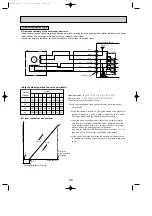
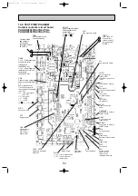
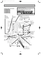
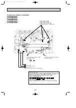
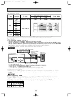
Outdoor Fan controller circuit board
PUHZ-RP200YHA
PUHZ-RP200YHA
1
PUHZ-RP200YHA
2
PUHZ-RP250YHA
PUHZ-RP250YHA
1
PUHZ-RP250YHA
2
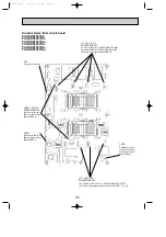
Brief Check of IGBT
W
Usually, they are in a state of being short-circuited if they are broken.
Measure the resistance in the following points (connectors, etc.).
If they are short-circuited, it means that they are broken.
Check of POWER MODULE
Check of IGBT circuit
P - U , P - V , P - W , N - U , N - V , N - W
Note:The marks, U , V and W
shown in the diagram above are not actually printed on the board.
1 2
1 2
5
3
1
N
U
W
TAB-U, TAB-V, TAB-W
Connect to the Fan motor (MF)
Voltage among phases : 20V-380V AC
CN6
Control signal from outdoor controller
circuit board (CN331)
CN2
Power supply from outdoor controller
circuit board (CN332)
+
+
-
}
}
282V DC
282V DC
}
565V DC
Connect to the outdoor Power circuit board (CN1)
CN5
P
(RED) (WHITE)(BLACK)
V
1
-
2
: 18V DC
[
2
: - ,
1
: + ]
OC338C-2.qxp 07.5.24 11:30 AM Page 56


