- 5 -
5.2 Installation of air cylinder assembly.
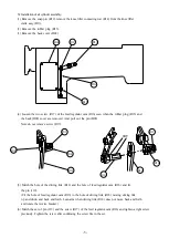
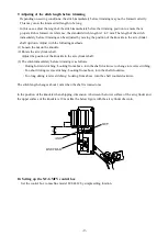
(1) Remove the snap pin (R12), remove the knee lifter connecting rod (R14) from the knee lifter
crank assy (R13).
(2) Remove the rubber plug (R15).
(3) Remove the back cover (D02).
(4) Loosen the two screw (R17) of the feed regulator cam (R16) seen when the rubber plug (R15) and
the back (D02) cover are removed. And, pull out the pin (D03).
Note do not remove screw (R17).
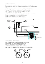
(5) Match the hole of the driving link (R18) and the hole of feed regulator cam (R16) and fix
the pin (119).
(Fit the hole of feed regulator cam (R16) to the hole of driving link (R18) moving driving link
up and down and back and forth. Lean arm when driving link (R18) does not move back and forth
and rotate the reverse bracket.)
(6) Match the set of pin (119) and the screw (R17) of the feed regulator cam (R16) and tighten a right screw
previously. Tighten the screw after confirming the screw fits in the set.
R15
R13
R12
R14
D02
D03
R18
R16
R17
R17
R16
R18
SET
119
Содержание LU-ST KIT
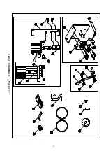
Страница 4: ...LU ST KIT Component Parts 3 ...
Страница 11: ...MEMO ...
Страница 12: ...PrintedinJapan ...

