background image

- 4 - 

5. Installation procedure of LU-ST KIT

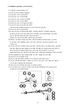
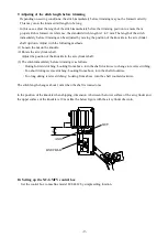
5.1  Exchange of thread  trimmer cam.  

(1)  Lean the sewing machine backwards. 

(2)  Loosen  the screw of bush  (R01). 

(3)  Loosen the screw of bush  (R02). 

(4)  Loosen the screw of feed cam  (R03). 

(5)  Loosen the screw of  bush  (R04).   

(6)  Loosen the screw of the large gear  (R05). 

(7)  Loosen the screw of eccentric cam  (R06). 

   (Lift the sewing machine and loosen the screw from the back side.)   

(8)  Loosen the screw of bush  (R07). 

(9)  Loosen the screw of spring holder  (R08).  And then detach  the coil  (R09)  spring and 

  pin  (R10), and  move the lower shaft right  to the place where thread trimmer cam  (D01) 

   remove with bush  (R04)  and thread release cam  (R11).   

  (Remove the eccentric cam  (R06)  and the large gear  (R05).) 

(10)  Remove  the thread trimmer cam  (D01)  with bush  (R04)  and thread release cam  (R11). 

   At that time, if the installation angle of the cam and bush is recorded, re-assembly work 

   become easy.   

(11)  Loosen  the screw of thread release cam  (R11),  and  then  remove the thread release cam  (R11) 

  with bush  (R04)  and thread trimmer cam  (D01).  Exchange the thread trimmer cam  (D01)  for   

  the kit  one  (105).  In thread trimmer cam  (105)  of the kit  has mark "2" to the side. 

  Install bush  (R04)  in the direction of the figure below. Afterwards, install thread release cam  (R11). 

(12)  Pass assembled the  bush  assembly  (R04,  105,  R11)  through the  lower  shaft.   

(13)  Move  the  lower  shaft left  slowly.   

(14)  Fix  the large gear  (R05). (Install it in the  direction of the figure below.)   

(15)  Fix the eccentric cam  (R06).

Tighten the screw in the groove of the shaft  at the right of 

        the feed bar connecting fork beforehand.


(16)  Move the lower shaft  left and return it  to former position. 

(17)  Put the first screw in  the set of lower shaft, and then tighten all of the loosened screw. 

 (Tighten the screw of bush (R07) finally.) 

R11 

D01

R04 

105 

R06  R05 

R03 

R02 R01 

R07 

R10 

R09 

R08 

SCREW 

Содержание LU-ST KIT

Страница 1: ...LOCKSTITCH COMPOUND FEED AUTOMATIC UNDERTRIMMER INDUSTRIAL SEWING MACHINE Attachment MODEL LU ST KIT INSTRUCTION MANUAL Short Thread Tail Device for LU2 4410 A180E547P03 ...

Страница 2: ...limination of additional hand trimming will increase production 4 Any damage to sewn parts caused by hand trimming will be eliminated 5 The Mitsubishi genuine knife mechanismprovides a reliable and durable trimfunction 2 Correspondence model Type Correspondence Control box LU ST KIT LU2 4410 B1T CS XC GMFY A sewing machine made in before April 1995 doesn t correspond to LU ST KIT 3 Specification 1...

Страница 3: ... cylinder assembly 1 109 M96062021 Screw 4 110 MP69A0601 Mounting plate 1 111 M95003017 Bolt 4 112 M90519050 Nylon washer 2 113 MP69A0603 Bracket 1 114 MP69A0237 Back cover 1 115 MP69A0910 Driving link 1 116 M91502045 Nut 1 117 M91503031 Bolt 3 118 MP69A1910 Link 1 119 M90910060 Pin 1 120 M91066004 Screw 4 121 MP69E0599 Solenoid valve assembly 1 122 MH25A1601 Solenoid value mounting plate 1 The pa...

Страница 4: ...LU ST KIT Component Parts 3 ...

Страница 5: ...stallation angle of the cam and bush is recorded re assembly work become easy 11 Loosen the screw of thread release cam R11 and then remove the thread release cam R11 with bush R04 and thread trimmer cam D01 Exchange the thread trimmer cam D01 for the kit one 105 In thread trimmer cam 105 of the kit has mark 2 to the side Install bush R04 in the direction of the figure below Afterwards install thr...

Страница 6: ...not remove screw R17 5 Match the hole of the driving link R18 and the hole of feed regulator cam R16 and fix the pin 119 Fit the hole of feed regulator cam R16 to the hole of driving link R18 moving driving link up and down and back and forth Lean arm when driving link R18 does not move back and forth and rotate the reverse bracket 6 Match the set of pin 119 and the screw R17 of the feed regulator...

Страница 7: ...e pin between nylon washer and nylon washer 10 Match the screw hole of the bracket 113 and the hole of the driving link 115 and tighten the bolt 117 11 Take out the machine head support on the table 12 Tighten all the screws of the back cover 114 and it is assembly completion 5 3 Exchange of feed dog fixed knife and needle plate Exchange parts of the figure below which you have for the one 101 102...

Страница 8: ...onnect the connector of solenoid value assembly 121 with option B of the control board 5 Connect the air supply source to the P port of the solenoid value 6 Use the regulator and the branch device which you prepared 5 5 Exchange of stitch length indicating plate 1 Turn the dial left and make the stitch length indicating plate to 0 points 2 Loosen the screw at the center of the dial and remove the ...

Страница 9: ...dle motion of the instruction manual for LU2 4410 8 Initial position of movable knife When you install this kit the position need not be adjusted Refer to install of movable knife of the manual for the exchange of the movable knife However the adjustment of the movable knife changes because the shape of the fixed knife changed Adjust to hide the point of the movable knife from the point of the bla...

Страница 10: ...e air cylinder shaft Adjust the position of the knuckle to the air cylinder shaft 3 The stitch immediately before trimming is as follows During forward stitching Looking from above turn the shaft clockwise to change to reverse stitching Too short during reverse stitching Looking from above turn the shaft clockwise Too long during reverse stitching Looking from above turn the shaft counterclockwise...

Страница 11: ...MEMO ...

Страница 12: ...PrintedinJapan ...

Отзывы: