


8 [BFM #1900 to #1927] PLC RUN>STOP Messages
70
FX
3U
-J1939 User's Manual
8. [BFM #1900 to #1927] PLC RUN>STOP Messages
FX
3U
-J1939 can transmit the message according to its state, if the PLC is in one of the following two states.
Up to four transmit messages can each be registered.
• If PLC state changes from RUN to STOP, the message registered into RUN>STOP messages 1 to 4 are
transmitted.
• If FROM/TO Watchdog in FX
3U
-J1939 has timed-out, the message registered in RUN>STOP messages 1
to 4 are transmitted.
Warning
Depending on PLC type and baud rate and bus load, FX
3U
-J1939 may be unable to send the message. In
such a case, additional H/W and/or S/W should be considered for safe system behavior.
If possible, use only one "RUN>STOP message" which will increase the possibility that the information is
transmitted in the event "RUN>STOP" occurs.
If more than one message is defined, messages are transmitted in order of priority "message 1" to "message 4."
Note
• In J1939 mode, the CAN-ID of PLC RUN>STOP messages are adjusted to J1939 Specification:
- The lowest byte of the CAN-ID will always equal the FX
3U
-J1939 current node address (BFM #28)
- If the PGN is in PDU1 format range (PF = HEF or less), the destination address is adjusted if the target
node changes its node address during dynamic address allocation. In this case, the node address is
displayed in BFM #1901/#1900, #1922/#1921 … as HFE until a valid address claim matching the
Remote ECU List entry is received.
For the required node address and ECU name definition, refer to Section 5.22
*1.
RTR is prohibited for these messages.
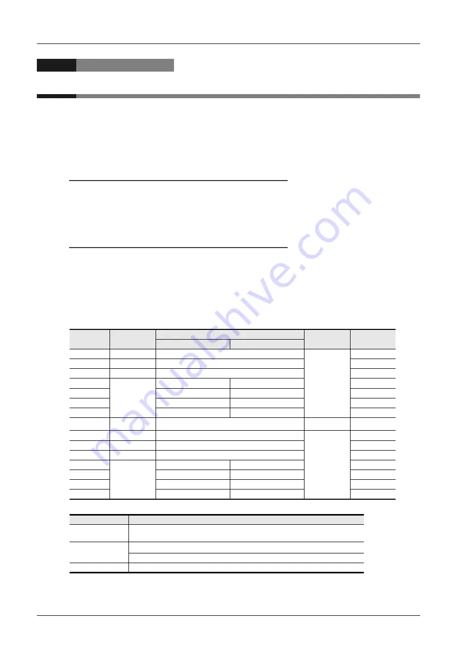
BFM No.
Function
Description
Message No.
Default Value
High Byte
Low Byte
BFM #1900
CAN-ID 1 LW
11/29 bit CAN-Identifier low word
RUN>STOP
message 1
HFFFF
BFM #1901
CAN-ID 1 HW
29 bit CAN-Identifier high word
HFFFF
BFM #1902
DLC
Data length count
H0
BFM #1903
Data bytes
2nd data byte
1st data byte
H0
BFM #1904
4th data byte
3rd data byte
H0
BFM #1905
6th data byte
5th data byte
H0
BFM #1906
8th data byte
7th data byte
H0
..…
..…
..…
..…
..…
BFM #1921
CAN-ID 4 LW
11/29 bit CAN-Identifier low word
RUN>STOP
message 4
HFFFF
BFM #1922
CAN-ID 4 HW
29 bit CAN-Identifier high word
HFFFF
BFM #1923
DLC
Data length count
H0
BFM #1924
Data bytes
2nd data byte
1st data byte
H0
BFM #1925
4th data byte
3rd data byte
H0
BFM #1926
6th data byte
5th data byte
H0
BFM #1927
8th data byte
7th data byte
H0
BFM Function
Description
11/29 bit CAN-ID n
CAN-ID is used to transmit this message into the network.
Sets HFFFF to the CAN-ID n LW and CAN-ID n HW when not using the message.
DLC
High byte H00 = send data frame
*1
Low byte = number of data bytes to transmit (K0 to K8)
Data bytes
Data bytes 1 to 8. Number of attached data bytes is defined by DLC.


