


146
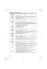
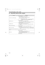
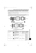
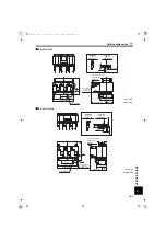
Measurement of main circuit voltages, currents and powers
Measuring Points and Instruments
5.2.1
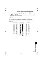
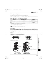
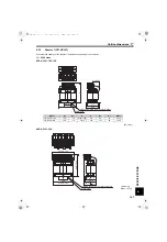
Insulation resistance test using megger
For the converter, conduct the insulation resistance test on the main circuit only as shown below and do not perform the test
on the control circuit. (Use a 500VDC megger.)
5.2.2
Pressure test
Do not conduct a pressure test. Deterioration may occur.
Item
Measuring Point
Measuring Instrument
Remarks
(Reference Measured Value)
Power supply voltage
V
1
Across R and S
Across S and T
Across T and R
Moving-iron type AC voltmeter
Commercial power supply
Within permissible AC voltage
fluctuation
(Refer to page 148)
Power supply side current
l
1
R, S, T line current
Moving-iron type AC ammeter
Power supply side power
P
1
R, S, T and
Across R and S
Across S and T Across T and R
Electrodynamic type single-
phase wattmeter
P
1
=W
11
+W
12
+W
13
(3-wattmeter method)
Power supply side power factor
Pf
1
Calculate after measuring power supply voltage, power supply side current and power supply side power.
Pf
1
=
100%
Converter output
Across P and N
Moving-coil type
(such as tester)
Converter LED display is lit.
1.35
V
1
Maximum 380V (200V class) and 760V
(400V class) during the regenerative
driving
Indicator signal
Across FM(+) and SD
Moving-coil type
(such as tester)
(internal resistance 50k
or
more)
Approximately 5VDC at maximum
frequency
(without indicator)
Pulse width T1: Adjust with
Pr. 900
Input signal
RES, SOF, X1, X2, Across
ROH(+) and SD
When open
20 to 30VDC
ON voltage: 1V or less
Fault signal
Across A and C
Across B and C
Moving-coil type
(such as tester)
Electric continuity check
[Normal]
[Abnormal]
Across A and C Discontinuity Continuity
Across B and C Continuity
Discontinuity
NOTE
Before performing the insulation resistance test on the external circuit, disconnect the cables from all terminals of
the converter so that the test voltage is not applied to the converter.
For the electric continuity test of the control circuit, use a tester (high resistance range) and do not use the megger or
buzzer.
3V
1
l
1
P
1
DC8V
T1
P/+
N/-
Inverter
Earth (ground)
500VDC
megger
Power
supply
Converter
R4/L14
S4/L24
T4/L34
HC2.book 146 ページ 2012年11月19日 月曜日 午前10時52分


