


108
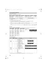
[Special monitor selection No.]
Refer to
for details of the monitor description.
Differ according to capacities. (55K or lower/75K or higher)
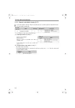
The regenerative status cannot be displayed. The regenerative status display is available only on the operation panel (FR-DU07-CNV).
Input terminal monitor details (when the terminal is ON: 1, when the terminal is OFF: 0,
: undetermined value)
Output terminal monitor details (when the terminal is ON: 1, when the terminal is OFF: 0,
: undetermined value)
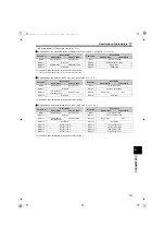
[Fault data]
Refer to
for details of fault description.
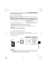
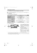
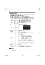
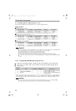
[Converter status monitor]
The signal within parentheses is in the initial status. Definitions change according to the
Pr. 11 to Pr. 16 (output terminal function selection).
b15
b0
RES
SOF
ROH
X2
X1
b15
b0
88R
ABC
Y3
Y2
Y1
CVO
RSO
RDY
Item
Instruction
Code
Bit
Length
Description
Example
Converter
status
monitor
H7A
8 bits
b0 : RDY(Inverter run permission)
b1 : Power driving
b2 : Regenerative driving
b3 : RSO (converter reset)
b4 : Y1 (overload)
b5 : Y2 (power supply phase
detecting)
b6 : CVO (converter running)
b7 : 88R (input contactor control)
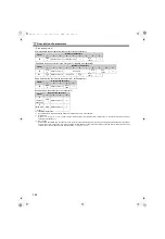
Converter
status
monitor
(expansion)
H79
16 bits
b0 : RDY (Inverter run permission)
b1 : Power driving
b2 : Regenerative driving
b3 : RSO (converter reset)
b4 : Y1 (overload)
b5 : Y2 (power supply phase
detecting)
b6 : CVO (converter running)
b7 : 88R (input contactor control)
b8 : ABC (fault)
b9 :
b10 :
b11 :
b12 :
b13 :
b14 :
b15 : Fault occurrence
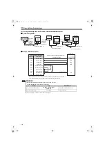
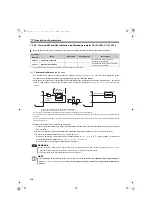
Data
Description
Increments
H01 Input current
0.01A/0.1A
H02 Input voltage
0.1V
H03 Bus voltage
0.1V
H05 Power supply frequency
0.01Hz
H06
Electronic thermal relay
load factor
0.1%
H07 Input power
0.01kW/
0.1kW
H08 Cumulative power
1kWh
H09
Cumulative
energization time
1h
Data
Description
Increments
H0A Input power
0.1kW/
H0F Input terminal status
H10 Output terminal status
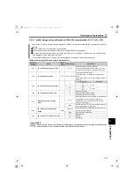
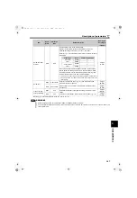
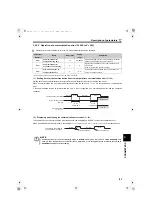
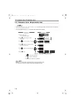
Data
Description
Increments
For read data H30B1
(Previous fault ...... THT)
(Latest fault ...... OPT)
0
1
0
1 0 0 0 0
0
1
1
0
0
0
1
1
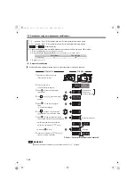
b15
b8b7
b0
Latest fault
(HB1)
Previous fault
(H30)
Fault record display example (instruction code H74)
Data
Description
H00
No fault
present
H11
E.OC2
H21
E.OV2
H30
E.THT
H40
E.FIN
H50
E.IPF
H51
E.UVT
H52
E.ILF
H90
E.OHT
HA3
E.OP3
HB0
E.PE
HB1
E.PUE
HB2
E.RET
HB3
E.PE2
HC0
E.CPU
HC1
E.CTE
HC2
E.P24
HC4
E.CDO
HC5
E.IOH
HF2
E.2
HF3
E.3
Data
Description
HF6
E.6
HF7
E.7
HF8
E.8
HF9
E.9
HFD
E.13
Data
Description
0
0
0
0
0
0
1
0
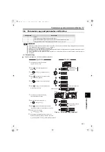
b7
b0
[Example 1] HO2: Power driving
[Example 2] H40: Converter running
0
1
0
0
0
0
0
0
b7
b0
0
0
0
0
0
0
1
0
b0
0
0
0
0
0
0
0
0
b15
[Example 1] HO2: Power driving
0
0
0
0
0
0
0
0
b0
1
0
0
0
0
0
0
1
b15
H8100: Trip by a fault
HC2.book 108 ページ 2012年11月19日 月曜日 午前10時52分


