


8
Technical Information
3
26
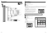
*1 Refer to the following section [Local system].
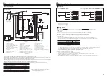
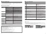
<Figure 3.2>
Note:
7RHQDEOHGUDLQLQJRIWKHF\OLQGHU
unit,
DQLVRODWLQJYDOYHVKRXOGEHSRVLWLRQHGRQERWKWKHLQOHWDQGRXWOHWSLSHZRUN
:LWKLQWKHEXLOGLQJEHVXUHWRLQVWDOODPDLQWDLQDEOHVWUDLQHU,WHPRQWKHLQOHWSLSHZRUNWRWKHF\OLQGHUXQLW6LPLODUO\RQWKHUHWXUQSLSHZRUNIURPVSDFHKHDWLQJ
FLUFXLWLWLVDOVRUHFRPPHQGHGWRLQVWDOODPDLQWDLQDEOHPDJQHWLFILOWHU,WHP
6XLWDEOHGUDLQSLSHZRUNVKRXOGEHDWWDFKHGWRDOOSUHVVXUHUHOLHIYDOYHVLQDFFRUGDQFHZLWK
national regulations.
:KHQXVLQJFRPSRQHQWVPDGHIURPGLIIHUHQWPHWDOVRUFRQQHFWLQJSLSHVPDGHRIGLIIHUHQWPHWDOVLQVXODWHWKHMRLQWVWRSUHYHQWDQ\
corrosive reaction
WDNLQJSODFH
ZKLFKPD\GDPDJHWKHSLSHZRUN
)LOOLQJORRSǯVIOH[LEOHKRVHPXVWEHUHPRYHGIROORZLQJWKHILOOLQJSURFHGXUH,WHPSURYLGHGZLWKXQLWDVORRVHDFFHVVRU\
,QVWDOOSULPDU\H[SDQVLRQYHVVHOWRWKHUHWXUQFLUFXLWRIVSDFHKHDWLQJDQG
ensure clear water
SDVVDJHEHWZHHQF\OLQGHUXQLWDQGSULPDU\H[SDQVLRQYHVVHO
Note:
0D[LPXPSULPDU\ZDWHUVXSSO\SUHVVXUHLVEDU03D
$WFRPPLVVLRQLQJVWDJHSOHDVHDGMXVWZDWHUSUHVVXUH
ZLWKLQSULPDU\FLUFXLWWREDUN3D
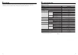
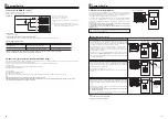
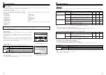
(+37490($!
Model name
EHPT20Q-VM2EA
Maximum
VHFRQGDU\SRWDEOHZDWHUVXSSO\SUHVVXUH
EDU03D
3ULPDU\H[SDQVLRQYHVVHOFKDUJHSUHVVXUH
EDUN3D
3ULPDU\SUHVVXUHUHOLHIYDOYHVVHWSUHVVXUH1RGHYLFHV
EDUN3D
Booster heater
VSHFLILFDWLRQ
N:9
3ULPDU\WKHUPDOVWRUHFDSDFLW\7DQNFDSDFLW\
/
NJ
Mass of the unit when full
0LQLPXPSULPDU\ZRUNLQJSUHVVXUH
EDUN3D
7DEOH!
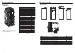
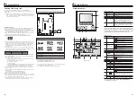
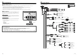
1. Plate heat exchanger
2. Booster heater with thermostat
3. Drain cock (Primary circuit)
4. Drain cock (Secondary (Potable) circuit)
5. Pump valve
6. Water circulation pump 1
(For thermal store and space heating)
7. Water circulation pump A
(For hot water supply to plate heat exchanger)
8. 3-way valve
9. Manometer
10. Primary pressure relief valve
11. Automatic air vent
12. Manual air vent
13. Drain valve (Primary circuit)
14. Strainer valve
15. Flow sensor 1 (For space heating)
16. Flow sensor A (Secondary (Potable) circuit)
17. Flow sensor B (Primary circuit)
18. Primary thermal store tank
19. THW1 (Flow water temp. thermistor)
20. THW2 (Return water temp. thermistor)
21. THW3 (Flow water temp. thermistor 2 (to tank))
22. THW4 (DHW supply temp. thermistor)
23. THW5A (Stored water temp. thermistor (upper))
24. THW5B (Stored water temp. thermistor (lower))
25. Electrical isolation pipe
26. Manual thermostat
27. Non-return valve
28. Filling loop (Accessory item)
29. Primary expansion vessel (Accessory item)
30. Discharge pipe (Local supply)
31. Tundish (Accessory item)
32. I solating valve (Local supply)
33. Thermo mix valve (recommended) (Local supply)
34. Magnetic filter (recommended) (Local supply)
35. Strainer (Local supply)
,
nlet
0DLQVZDWHUVXSSO\
Outlet
DHW
18
1
2XWGRRU8QLW
48+=:9$
㻖䠖
Locally su
SS
lie
G
Water
SLS
e
13
19
27
*
1
2
21
22
23
3
2
11
7
12
27
3
8
6
29*
*
32*
32*
32*
33*
32*
32*
9
3D
12
3
17
16
Local system*1
HEX
&\OLQGHU8QLW
(+37490($
7RG
rain
7RG
rain
)OH[LEOHKRVH
7HPSRUDU\FRQQHFWLRQ
0DLQV:DWHUVXSSO\
28*
31*
31*
7RG
rain
Ű
Water circuit diagram
0D[LPXPSULPDU\ZRUNLQJSUHVVXUH
EDUN3D
9
Technical Information
3
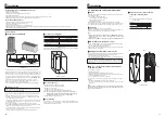
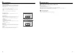
1-zone temperature control
1
Zone1
2
4
Zone1
Zone2
3
1
1
1-zone temperature control (2-zone valve ON/OFF control)
1. Heat emitters (e.g. radiator, fan coil unit) (local supply)
2. Zone1 2-way valve (local supply)
3. Zone2 2-way valve (local supply)
4. Auto-bypass valve (local supply)
End user can monitor accumulated*1 ‘Consumed electrical energy’ and ‘Delivered energy’ in each operation mode*2 on the main controller.
*1 Monthly and Year to date
*2 - DHW operation
- Space heating
Refer to “5.7 Main controller” for how to check the energy, and “5.1 DIP switch functions” for the details on DIP-SW setting.
Either one of the following two method is used for monitoring.
Note: The method 1 should be used as a guide. If greater accuracy is required, then method 2 should be used.
Note: Consumed electric energy of pump A is automatically calculated by the system.
Booster heater
Pump1*1
Default
2kW
***(factory fitted pump)
EHPT20Q-VM2EA
2kW
***
<Table 3.5>
*1 "***" displayed in the energy monitor setting mode means the factory fitted pump is connected as pump 1 so that the input is automatically calculated.
When anti-freeze solution (propylene glycol) is used for primary water circuit, set the produced energy adjustment if necessary.
For further detail of above, refer to “5.7 Main controller”.
2. Actual measurement by external meter (locally supplied)
FTC has external input terminals for 2 ‘Electric energy meters’ and a ‘Heat meter’.
If two ‘Electric energy meters’ are connected, the 2 recorded values will be combined at the FTC and shown on the main controller.
(e.g. Meter 1 for main power line, Meter 2 for booster heater power line)
Refer to the [Signal inputs] section in “5.2 Connecting inputs/outputs” for more information on connectable electric energy meter and heat meter.
1. Calculation internally
Electricity consumption is calculated internally based on the energy consumption of outdoor unit, electric booster heater, pump1 and other auxiliaries.
Produced heat is calculated internally by multiplying delta T (Flow and Return temp.) and flow rate measured by the factory fitted sensors.
Set the electric booster heater capacity and water pump(s) input according to indoor unit model. (Refer to the menu tree in “5.7
Main controller”)
Ű
Local system
Ű
Energy monitoring


