

26
Main
menu
<Continued from the previous page.>
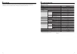
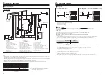
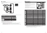
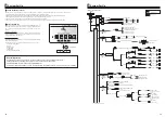
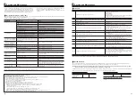
<Main Controller Menu Tree>
Unrestricted access
Installer only
Main screen
Initial
Main
menu
Service
Password
protected
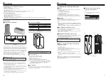
Manual operation
Function settings
Thermistor adjustment
Economy settings for pump
Electric heater (Heating)
Standard (Heat pump & electric heater)/Heater (Electric heater only)
Freeze stat function
Energy monitor
settings
Running information
Thermistor reading
Summary of settings
Error history
Password protection
Manual reset
SD card
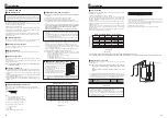
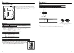
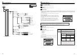
Heating
operation
H/P thermo diff.adjust
Flow temp.range
Room temp.control
Auxiliary settings
Heat source setting
Pump speed
Operation settings
ON/OFF
Delay
ON/OFF
Delay
Flow t.
Outdoor ambient temp.
Electric heater
capacity
Main controller
SD
Yes/No
Select download data
FTC
Main RC
SD
Yes/No
Select upload data
Water pump input
Electric energy meter
Booster heater 1 capacity
Pump 1
Min.temp.
ON/OFF
Mode
Interval
Flow rate setting(Heating)
Mode
Flow rate
Max.temp.
Lower limit
Upper limit
<See
section>
Menu
Delivered energy adjustment
Heat meter
Main RC
Long press
F1
F2
F3
F1
F2
F3
System Set Up
5
Long Press
Short Press
27
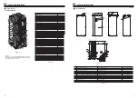
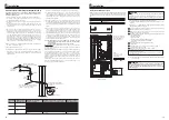
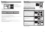
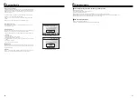
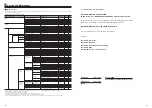
Time/Zone schedule setting screen
Preview screen
Schedule timer
Setting the schedule timer
Ź)RUIXUWKHUGHWDLODERXWRSHUDWLRQUHIHUWR2SHUDWLRQPDQXDO
Ź)RUIXUWKHUGHWDLODERXWRSHUDWLRQUHIHUWR2SHUDWLRQPDQXDO
Domestic Hot Water (DHW)
Heating
Holiday mode
Ź)RUIXUWKHUGHWDLODERXWRSHUDWLRQUHIHUWR2SHUDWLRQPDQXDO
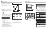
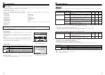
Menu subtitle
Description
Room RC zone
select
Sensor setting
&RQWURORSWLRQ
(
SDJH
)
Corres
SRQGLQJ
init
LDO
settings room
sensor
=RQH
Zone 2
A
5RRP5&RQH
HDFKIRU=RQH
DQG=RQH
B
7+
C
When di
IIHUHQWURRP
VHQVRUVDUHXVHG
DFFRUGLQJWRWKHWLPH
schedule
Time/ Zone*2
)URPWKH,QLWLDOVHWWLQJVPHQXWKHLQVWDOOHUFDQVHWWKHIROORZLQJ
)ROORZWKHSURFHGXUHGHVFULEHGLQ*HQHUDO2SHUDWLRQIRUWKHVHWXSRSHUDWLRQ
<Room sensor settings>
Initial Settings
7KHVFKHGXOHWLPHUIRUVSDFHKHDWLQJDQG'+:DUHVHWLQWKHRZHYHUIRU'+:RQO\WLPHFDQEHXVHGDVVFKHGXOLQJYDULDEOH
$VPDOOUXEELVKELQFKDUDFWHULVDOVRGLVSOD\HGFKRRVLQJWKLVLFRQZLOOGHOHWHWKHODVWXQVDYHGDFWLRQ
,WLVQHFHVVDU\WRXVHWKH6$9(IXQFWLRQ)EXWWRQWRVDYHVHWWLQJV&21),50GRHVQRWDFWDV6$9(IRUWKLVPHQX
'DWH7LPH
6XPPHUWLPH
7HPSGLVSOD\
&RQWDFWQXPEHU
7LPHGLVSOD\
&)
5RRPVHQVRUVHWWLQJV
:KHQ]RQHYDOYHRQRIIFRQWUROLVDFWLYHDQGZLUHOHVVUHPRWH
FRQWUROOHUVDUHDYDLODEOHIURP5RRP5&]RQHVHOHFWVFUHHQ
select zone
1RWRDVVLJQWRHDFKUHPRWHFRQWUROOHU
)URPVHQVRUVHWWLQJVFUHHQVHOHFWDURRPVHQVRUWREHXVHGIRU
PRQLWRULQJWKHURRPWHPSHUDWXUHIURP=RQHDQG=RQHVHSD
UDWHO\
)RUURRPVHQVRUVHWWLQJVLWLVLPSRUWDQWWRFKRRVHWKHFRUUHFWURRPVHQVRU
GHSHQGLQJRQWKHKHDWLQJPRGHWKHV\VWHPZLOORSHUDWHLQ
1RWVSHFLILHGLIDORFDOO\VXSSOLHGURRPWKHUPRVWDWLVXVHG
5RRP5&RQHHDFKIRU=RQHDQG=RQHLIDZLUHOHVV
UHPRWHFRQWUROOHULVXVHGDVDURRPWKHUPRVWDW
)URPVHQVRUVHWWLQJVFUHHQVHOHFW7LPH=RQHWRPDNHLW
SRVVLEOHWRXVHGLIIHUHQWURRPVHQVRUVDFFRUGLQJWRWKHWLPH
VFKHGXOHVHWLQWKH6HOHFW7LPH=RQHPHQX7KHURRP
VHQVRUVFDQEHVZLWFKHGXSWRWLPHVZLWKLQKRXUV
6FKHGXOHGWLPHUFDQEHVHWLQWZRZD\VIRUH[DPSOHRQHIRUVXPPHUDQGWKHRWKHUIRUZLQWHU5HIHUWRDV6FKHGXOHDQG6FKHGXOHUHVSHFWLYHO\2QFHWKHWHUP
PRQWKVIRUWKH6FKHGXOHLVVSHFLILHGUHVWRIWKHWHUPZLOOEHVSHFLILHGDV6FKHGXOH,QHDFK6FKHGXOHDQRSHUDWLRQDOSDWWHUQHDWLQJ'+:FDQEHVHW
,IQRRSHUDWLRQDOSDWWHUQLVVHWIRU6FKHGXOHRQO\WKHSDWWHUQIRU6FKHGXOHZLOOEHYDOLG,I6FKHGXOHLVVHWWRIXOO\HDULH0DUFKWR)HERQO\WKHRSHUDWLRQDOSDWWHUQ
IRU6FKHGXOHZLOOEHYDOLG
)ROORZWKHSURFHGXUHGHVFULEHGLQ*HQHUDO2SHUDWLRQ3DJH
)
IRUWKHVHWXSRSHUDWLRQ
7KHSUHYLHZVFUHHQDOORZV\RXWRYLHZWKHFXUUHQWVHWWLQJV,Q]RQHKHDWLQJRSHUDWLRQ
SUHVV)WRVZLWFKEHWZHHQ=RQHDQG=RQH'D\VRIWKHZHHNDUHGLVSOD\HGDFURVVWKH
WRSRIWKHVFUHHQ:KHUHGD\DSSHDUVXQGHUOLQHGWKHVHWWLQJVDUHWKHVDPHIRUDOOWKRVH
GD\VXQGHUOLQHG
+RXUVRIWKHGD\DQGQLJKWDUHUHSUHVHQWHGDVDEDUDFURVVWKHPDLQSDUWRIWKHVFUHHQ
:KHUHWKHEDULVVROLGEODFNVSDFHKHDWLQJ'+:ZKLFKHYHULVVHOHFWHGLVDOORZHG
:KHQVFKHGXOLQJKHDWLQJEXWWRQ)FKDQJHVWKHVFKHGXOHGYDULDEOHEHWZHHQWLPHDQG
WHPSHUDWXUH7KLVHQDEOHVDORZHUWHPSHUDWXUHWREHVHWIRUDQXPEHURIKRXUVHJDORZHU
WHPSHUDWXUHPD\EHUHTXLUHGDWQLJKWZKHQWKHRFFXSDQWVDUHVOHHSLQJ
System Set Up
5


